TERABEAM Marquee EX User Manual Download Page 10


Marquee™ Point-to-Point Series User Guide 

The antenna can be mounted either vertically or horizontally polarized.  If you are using a Marquee with a 
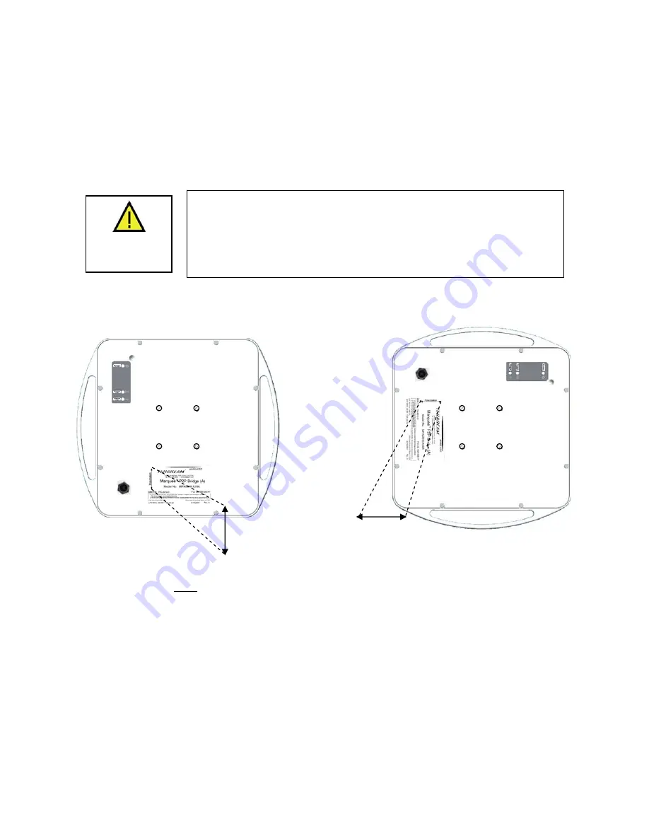
23 dBi FP attached antenna, the label located on the back of the unit shows an arrow indicating the 
antenna’s polarization (see Figures 2.7a and b).  Please note that both ends of the link must use the 
same polarization.  Be aware that most omni antennas are vertically polarized and if the Marquee EX is 
aimed at one, it must be installed vertically polarized, i.e., with the polarization arrow up and down. If you 
are using a Marquee with an external antenna, there is no arrow on the label located on the back of the 
unit and an additional N-type female jack is present to connect a short coax cable to the antenna (see 
Figure 2.1b).  All previous considerations regarding polarization are applicable to the external antenna. 


Figure 2.7 – Marquee EX With Attached Antenna Orientation 


(a) For Vertical Polarization 


(b) For Horizontal Polarization 

Polarization 

Arrow 

Polarization 

Arrow 


WARNING 

If you are using a Marquee with an external antenna, the unit must be 
operated with a proper antenna, microwave load or terminator plugged 
into the N-type female jack on the back of the unit. Operating the 
Marquee with nothing connected to the jack may result in damage to the 
TX section of the unit which will not be covered by the factory warranty 
and will be a billable repair. 

1.  Fit the adaptor bracket (A) to the four studs protruding from the back of the Marquee EX unit, by 

aligning the four inner holes with the mounting studs on the back of the unit and securing to the u
using four nuts, lock washers, and flat washers, as shown in Figure 2.8. Tighten hardware (four 
places). 

IMPORTANT: 

Note the position of the serrated edge of bracket (A). 

Attach the pole mounting bracket (B) to adaptor bracket (A) by using one M8x

nit 


40 bolt and flat washer 


s, 

ng 

2

on one side, and nut, lock washer and flat washer on the other, as shown in Fig 2.8. Tighten hardware
(one place). 

IMPORTANT: 

Ensure that the serrated edges on both brackets are facing each other. 

Fasten the unit to the pole using pole clamp (C) and two M8x70 bolts, lock washers, and flat washer

3

as shown in Fig 2.9. Tighten hardware (two places). The pole mounting bracket (B) will accept pole 
diameters between 1.75” to 3” OD. You may attach the Marquee unit to smaller diameter poles, 
between 1” to 1.75” OD, by flipping over the pole clamp (C) so the convex part faces the pole and 
using two M8x40 bolts. The Marquee unit can also be mounted to larger pole diameters by discardi
pole clamp (C) and replacing it with metal straps (not included) fastened through slots located on the 
pole mounting bracket (B). 

Version 1.2 

Page 7 

February 2005 

Summary of Contents for Marquee EX

Page 1: ...e Point to Point Series User Guide Contact Terabeam www terabeam com 8000 Lee Highway Falls Church VA 22042 Office 703 205 0600 Fax 703 205 0610 Sales 1 888 297 9090 MNL 500274 001 Version 1 2 Februar...

Page 2: ...ther rights that vary from state to state This warranty is only extended to purchases made in the United States of America or its possessions SPECIAL WARRANTY NOTICE The warranty is null and void if a...

Page 3: ...tor 15 3 3 Configuring the Marquee 16 Appendix A Marquee Technical Specifications 19 2005 Terabeam Wireless All Rights Reserved No part or parts of this document may be reproduced translated stored in...

Page 4: ...ures 1 1a and b The FP enclosure features a 23 dBi integrated antenna The EX enclosure comes either with a 23 dBi flat panel antenna attached to the top of the unit or it has an N type connector on th...

Page 5: ...VAC to 48 VDC power supply two each CD ROM with Windows based Configurator software User s Manual A Terabeam outdoor Ethernet cable must be ordered separately per unit Available lengths are 50 100 20...

Page 6: ...network that resembles your actual configuration as close as possible By using such a mock up troubleshooting potential problems will be much easier than if you already installed the equipment in the...

Page 7: ...daptor bracket B a pole clamp C and a U bolt D Figure 2 2 shows the hardware provided to mount the Marquee FP unit Pole Clamp C U Bolt D Pivot Adaptor Bracket B Pole Mounting Bracket A he integrated a...

Page 8: ...ion the bracket so that the side that has the circular tab is pointing towards the center of the unit Secure to the unit by threading two nuts and tighten them firmly with an appropriate wrench 2 Atta...

Page 9: ...be properly water proofed with all weather electrical tape Permagum or equivalent Do not use Silicon glue The Marquee EX unit is installed by using an X shaped adaptor bracket A that is secured to the...

Page 10: ...hing connected to the jack may result in damage to the TX section of the unit which will not be covered by the factory warranty and will be a billable repair 1 Fit the adaptor bracket A to the four st...

Page 11: ...the unit making sure the notch on the connector is correctly aligned with the tab on the jack as shown on Figure 2 10 Turn the round locking nut clockwise as you push in until it securely fastens onto...

Page 12: ...5 DC Powe Protecte If you are using a Marquee unit with an external antenna connect the antenna to the N type female jack on the back of the unit RJ 45 Ethernet Connector To Switch Router or PC To Ma...

Page 13: ...isplayed of the power supply to the DC Power jack on the Cat 5 DC Power pply into an AC outlet Check that the red Power LED on the Marquee r the wireless medium the green Wireless Link LED should be f...

Page 14: ...Marquee in onto the local unit Fig 2 13 Click the Analyze tab then click the Wireless Link Test button Enter IP Address window appe 3 Log The ars Fig 2 14 The IP address and the password should be e c...

Page 15: ...lick the Link Test button or double click the partner unit The Remote Test Li 16 The main goal now is to peak the SNR levels at both ends of the link Figure 2 15 Select a Remote Link Partner Screen 4...

Page 16: ...weep in both azimuth and elevation is made in order to identify these false peak SNR readings so to zero in on the true peak alignment reading due to the main antenna beam 10 Tighten the two Azimuth a...

Page 17: ...Line of Sight Adjustment for Signal Optimization EX Enclosure Rotate in this plane for azimuth alignment Rotate in this plane for elevation alignment Elevation adjustment bolt Azimuth adjustment bolt...

Page 18: ...3 The InstallShield Wiza cate successful installation of the Configurato to complete the installation 3 2 After igurator installation you gure your M following steps provide a quick pro started For m...

Page 19: ...this button 5 afe place onfigured for operation Marquee Bridge P P 2 each The default read write password is public S IP addresses Read Write password Radio frequency channel 1 Co t a crossover Ether...

Page 20: ...Click on Setup 2 The IEEE 802 11 Setup screen appears see Figure 3 5 Select the type of Station this Marquee is going to be In a P P configuration one unit must be Base and the other must be 9 Click...

Page 21: ...value Click OK Figure 3 7 TurboCell Advanced Setup Screen Figure 3 8 System Access Setup Network ID 1 from 0 through 15 to identify your network Both units in a link must be configured with the same...

Page 22: ...tomatic channel searching CPEs Yes Encryption DES 56 bit Blowfish 128 bit AES 128 Bit Upgradeable Q4 04 Note Encryption option lowers throughput since it is done in software Watchdog Reboot Timer Yes...

Page 23: ...389 x 389 x 29 mm EX E x 3 25 in 305 x 356 x 83 mm nclosure 15 nclosure 12 x 14 nclosure 2 90 lbs 1 32 Kg nclosure 9 65 lbs 4 38 Kg or all weather LED status indicators Pow ireless Link and Ethernet...

Page 24: ...ivity3 7 8 4 dB 3 dB ve Level 30 dB Over The Air D U tab p to 54 M ctab PSK sion for s for a 3 6 Versio Thro r s e channel Modulation Scheme OFDM SK Radio Operation Time Duplex TDD Time Division Duple...

Reviews: