background image

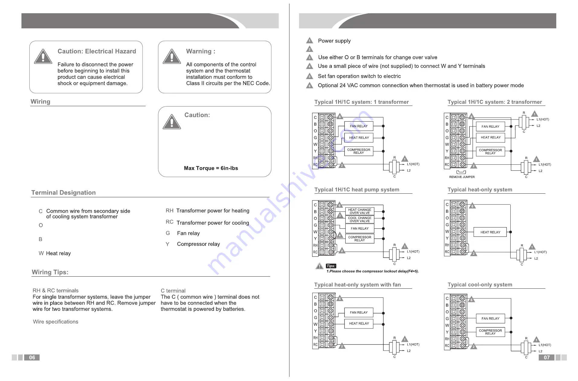
6. Wiring

7. Wiring Diagrams

Jumper inatalled on 1-tranformer system and removed on 2-transformer system

1. If you are replacing a thermostat. take

note of the terminal connections, the 

wiring connections may not be color 

coded. For example, the Green wire

may not be connected to the G terminal.

2. Loosen the terminal block screws. insert

wires then retighten terminal block screws.

3. Place nonflammable insulation into wall

opening to prevent drafts.

Use shielded or non-shielded 18-22 gauge thermostat wire.

Do Not over tifhten terminal block

screws, as this can damage 

terminal block. Keep the correctly 

fitted to the base to avoid operation 

issues.

Heat pump changeover value

energized for cooling
Heat pump changeover vavle energized 

for heating

Summary of Contents for CPT11

Page 1: ...s thermostat operates on last up to 1 year The battery voltage symbol will flash to indicate when batteries need replacement When the battery voltage symbol flashes change batteries as soon as possible 3 When changing batteries replace batteries within 20 minutes of removing the old ones to maintain programmed settings such as time and date 4 The thermostat is shipped with a protective film on the...

Page 2: ...hange Filter symbol is displayed the number of the days set for filter change interval time has elapsed TENZA Up button In heating cooling mode the Up button raises the temperature setting When programming the Up button will also be used for changing system parameters Down button In heating cooling mode the Down button lowers the temperature setting When programming the Down button will be used fo...

Page 3: ...Close to hot or cold air ducts In direct sunlight On an outside wall In a corner or behind a door Where there are concealed chimneys or pipes in the wall behind Select an appropriate location The temperature of the location should be representative of the building Insert a screwdriver into the slot and pry up the front part of the panel to open it For horizontal mount put one screw left in the lef...

Page 4: ...ted to the G terminal 2 Loosen the terminal block screws insert wires then retighten terminal block screws 3 Place nonflammable insulation into wall opening to prevent drafts Use shielded or non shielded 18 22 gauge thermostat wire Do Not over tifhten terminal block screws as this can damage terminal block Keep the correctly fitted to the base to avoid operation issues Heat pump changeover value e...

Page 5: ...setting interface and the changed parameters will not be saved When the power is on in cool heat mode hold SET for 5 seconds to enter the programming mode LUVW VHW WKH V VWHP FORFN ZKHQ WKH FORFN DUHD LV IODVKLQJ SUHVV ȁ RU 9 WR FKDQJH WKH FORFN QG LI RX KROG ȁ RU 9 WKH DGMXVPHQW ZLOO EH DFFHOHUDWHG 3UHVV 6 7 DJDLQ WR VHW WKH ZHHN ZKHQ WKH ZHHN LV IODVKLQJ SUHVV ȁ RU 9 WR FKDQJH the day of the wee...

Page 6: ... at 30 right to the snaps Step 3 Press the lower part front of the display panel to complete the installation 6 Select filter change counter Select F8 0 the backlight will turn off in 5 seconds Select F8 1 backlight will be always on With the power off hold F button for 5 seconds Symbol dE will be displayed in thr temperature area then press RUN key to confirm and exit High quality alkaline batter...

Reviews: