OPERATION EN
17
OS3 DM20036 (1
−
2018)
REPLACING THE e
−
CELL
Requires service kit AS20041 E
−
CELL
REPLACEMENT
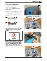
Refer to the
Wear Component
Indicators panel on
the touch screen display for status of system wear
components. Order a replacement e
−
cell when
the remaining segment on the progress bar turns
yellow. Replace the e
−
cell when the the segment
turns red.
Order new e
−
cell
(yellow)
Replace e
−
cell
(red)
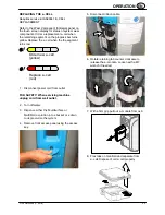
1. Disconnect power cord from outlet.
FOR SAFETY: When servicing machine
unplug cord from wall outlet.
2. Turn off water.
3.
Dispense either the MultiSurface or
MultiMicro solution into a bucket or a drain
to depressurize the system.
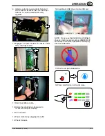
4. Remove front access panel using the access
key.
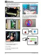
5. Disconnect ribbon cable.
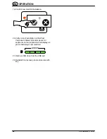
6. Rotate retaining tab counter clockwise to
release the e
−
module. Loosen with a M7
wrench if needed.
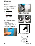
7. With a firm grip pull out e
−
module from os3.
8. Flex tabs on manifold and separate from
e
−
cell. Dispose of old e
−
cell properly.


