background image

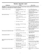
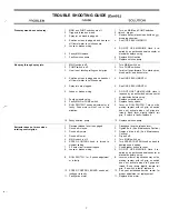
TROUBLE SHOOTING GUIDE

WARNING!!! To avoid serious personal injury: Disconnect power before servicing. Electrical service must be
performed by an authorized service station or electrician.

Nothing runs, there is no power.

1.

MAIN switch is off or faulty.

2.

Power cord wire(s) have come loose from
MAIN switch.

3. Fuse blown or circuit breaker tripped in

building.

4.

Short in power cord.

1.

Turn on MAIN switch or replace.

2.

DO NOT USE MACHINE. Have it 

paired by an authorized service center or
electrician before using.

3.

Reset breaker and plug machine into a

circuit which is not as heavily loaded.

4.

Replace power cord.

Brush motor does not run.

1.

1.5 amp brush circuit breaker tripped 

1.

There are several reasons why this circuit

cause:

breaker could trip:

Brush is adjusted too low.

See ADJUSTING BRUSH HEIGHT on

page 2.

Brush motor runs but brush does not spin.

Brush is clogged with carpet strands or

UNPLUG POWER CORD and remove

other debris.

all clogging debris wrapped around
brush.

There is 

dead short in the wiring.

DO NOT USE MACHINE. Have it re-

paired by an authorized service center or

electrician before using.

2.

PUMP switch is off or faulty.

2.

Turn on PUMP switch. This switch acti-
vates spray jets and brush drive motor
when you twist roll grips. Replace switch

if faulty.

3.

ROLL SWITCH 1 (left side) needs 

3.

Lever on ROLL SWITCH 1 may not be

ment or is faulty.

making contact with roll grip so switch
does not activate when roll grips are

turrned. Bend lever slightly toward roll
grip. If switch is faulty, replace it.

4.

Loose wiring connection or broken wire.

4. DO NOT USE MACHINE. Have it re-

paired by an authorized service center or
electrician before using.

5.

Faulty brush motor.

5.

Replace brush motor.

1.

Brush drive belt is loose or broken.

1.

If belt is loose, loosen brush motor mount-
ing nuts then pivot motor until belt is tight.
If belt is broken, replace.

2.

Set screws for brush pulley or motor pulley

2.

Tighten set screws.

have loosened.

Vacuum motor does not run.

Vacuum motor runs but there is little or no
suction.

1.

VACUUM switch is off.

1.

Turn on VACUUM switch.

2.

VACUUM switch is faulty.

2.

Replace faulty switch.

3.

Loose wiring connection or broken wire.

3.

DO NOT USE MACHINE. Have it re-

paired by an authorized service center or
electrician before using.

4.

Faulty vacuum motor.

4.

Replace vacuum motor.

1.

Recovery tank is full and the auto shutoff

1.

Empty recovery tank.

float has shut off suction.

2.

Vacuum pickup head is clogged.

2.

Raise pickup head and use a coat hanger

or other tool to remove clogging material.

3. Vacuum hose has come loose from

vacuum pickup head.

4.

Vacuum hose has a loose cuff or it has a
hole.

5.

Vacuum hose is not inserted tightly into
clear recovery dome.

6.

Clear recovery dome is loose.

3.

Push hose firmly onto vacuum pickup
head.

4.

Tighten hose cuff or replace hose.

5.

Push hose firmly into dome.

6.

Tighten two knobs on clear dome.

Reverse release lever is hard to engage.

1.

Belt tension is too tight.

1.

Readjust belt tension. 

(See Maintenance

Section.)

6

Summary of Contents for castex falcon 2800 WF2800

Page 1: ...by Michigan Company Inc 2011 N High St Lansing Mich 48906 517 484 9312 ht p l vwnv Michco Com Email Shop Michco Com c 1998 by Michco Others CASTEX INCORPORATED 12875 RANSOM STREET HOLLAND MI 49424 A m...

Page 2: ...RCE 2 ADJUSTING BRUSH HEIGHT 2 PRESPRAY WHILE CLEANING 2 CLEANING CARPET 3 CIRCUIT BREAKERS 3 CLEANING UPHOLSTERY 3 DRAINING RECOVERY TANK 4 MAINTENANCE AFTER EACH USE 5 EVERY FORTY HOURS OF OPERATION...

Page 3: ...ay jets can become plugged If you do use powders always pre mix them in a bucket until they are completely dissolved before pouring into the extractor s solution tank A CAUTION Use separate buckets to...

Page 4: ...0 GROUNDING BLADE Fig 5 0 1 0 p J Fig 6 ADJUSTING BRUSH HEIGHT 1 Lower brush Pull back on lever and depress thumb latch then move lever forward to lower Figure 7 2 Rotate SPEED CONTROL KNOB to slowest...

Page 5: ...UTION Do Not allow foam to enter shut off float Foam will not shut off shut off float Foam will damage vacuum motor and this damage is NOT COVERED BY WARRANTY 8 To check remaining cleaning solution in...

Page 6: ...ure 14 6 Overlap strokes to avoid streaking Use as little clean ing solution as possible AVOID GETTING UPHOL STERY TOO WET 2 If there is leftover cleaning solution in solution tank drain excess soluti...

Page 7: ...hrough spray jets for several seconds Allow solution to remain in system over night in above freezing temperatures Later drain solution then run 3 gal 13 L of clean water through system to flush out i...

Page 8: ...ing contact with roll grip so switch does not activate when roll grips are turrned Bend lever slightly toward roll grip If switch is faulty replace it 4 Loose wiring connection or broken wire 4 DO NOT...

Page 9: ...CH MONTH DO NOT USE THE MACHINE Have it repaired by an authorized service center or electrician before using Replace solenoid valve Replace faulty switch Lever on ROLL SWITCH 1 may not be making conta...

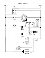
Page 10: ...IAGRAM Kp BLK A 5 3 v 0 VACUUM MAIN PUMP SWITCH SWITCH I J I SWITCH B L K B L K W H T BLK POTENTIOMETER 230 V BLK rr I I r BLK IIII II A1 SPEED CONTROL BOARD LK I I II BLK I GRN GRN 1 r GRN 1 SOLUTION...

Page 11: ...LINE 1 LINE 2 MAIN SWITCH VACUUM SWITCH SPEED CONTROL BOARD TERMINALS AC AC A A F HI W LO III I I I I III I I ROLL SWITCH 1 CIRCUIT BREAKER 2 5 AMP CIRCUIT BREAKER 1 5 AMP I ROLL SWITCH 2 BRUSH MOTOR...

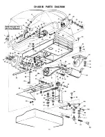
Page 12: ...CHASSIS PARTS DIAGRAM I 54 45 44 1 y 1 93 28 83 J 103 4 104 F 105 I 106...

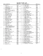
Page 13: ...EL 103002 1 40 WASHER FLAT 3 a 140028 4 41 WASHER SPLIT LOCK 3 a S S 140017 4 97 BUSHING 140139 2 42 NUT HEX 3 a 16 140525 4 98 SCREW 5 l 6 l 8X3 4 140223 4 43 44 45 46 47 48 49 50 51 52 53 MOTOR GEAR...

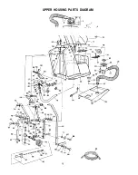
Page 14: ...UPPER HOUSING PARTS DIAGRAM 3 J7 U J 8 e12 15 I I i 7 332 27 i 65...

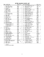
Page 15: ...49 ELBOW 3 8MX1 2H 90 DEG NYLN 150425 2 50 HOSE 3 8 LP GRAY BULK 160207 1 083 51 CLAMP HOSE 140301 1 52 HOSE BARB 1 4F X 3 8H 150511 1 53 NIPPLE l 4 CLOSE 150615 1 54 ADAPTER ll4F X 1 4M 150000 1 55...

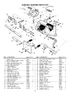
Page 16: ...0241 2 19 SCREW 10 24X112 140890 2 20 NUT KEP 1 O 24 140519 2 21 BOARD CONTROL W POT KNOB 130379 1 22 NUT CONDUIT LOCK l 2 140504 1 23 HARNESS WIRING 130855 1 24 CLAMP INSULATED 3 4 ID 140314 1 25 TUB...

Page 17: ...8 2 230411 1 130471 1 190150 1 10 A NOZZLE BRASS 80015 201011 6 1 MOTOR BRUSH DRIVE 230 VOLT 130472 1 11 CORD GRIP 1 2N NYL BK 130181 1 I BRUSH CARD FOR 130472 190154 1 12 CORD 18 3 BLACK BULK 130939...

Page 18: ...PUMP HOUSING 190130 1 2 KIT UPPER PUMP HOUSING 190128 1 6 PUMP 100 PSI 120V COMPLETE 180103 1 KIT CHECK VALVE ONLY 190124 1 PUMP 100 PSI 220V COMPLETE 180109 1 DECAL PARTS LIST NOT SHOWN DESCRIPTION...

Page 19: ...200912 1 5 SCREW 1 4X3 4 140554 2 6 TRIGGER FLOOR TOOL 200902 1 7 SLEEVE TRIGGER 200809 1 8 PIN 140605 1 NUT PUSH 140520 2 9 VALVE FLOW CONTROL 210150 1 10 KIT VALVE PIN SPRING 190603 1 11 CAP HEX VAL...

Page 20: ......

Reviews: