background image

HYDRAULICS

5-14

ATLV 4300 330495 (10--98)

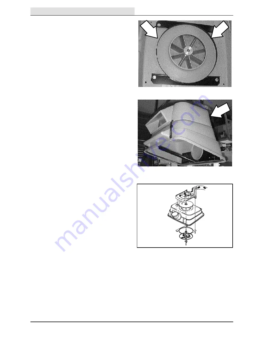
19. After the screen has been tighten down,

center the string guard (on the retainer

plate) around the outside of the screen.

Tighten the four screws to 18 -- 24 Nm

(15 -- 20 ft. lb).

20. Reinstall cover assembly onto the hopper

plenum.

21. Reinstall six hex screws holding the cover

assembly to the hopper plenum. Tighten the

screws to 18 -- 24 Nm (15 -- 20 ft. lb). Use

blue loctite (242) on the threads of this

hardware.

NOTE: Observe hydraulic cleanliness

requirements when opening hydraulic lines.

22. Reconnect the hydraulic lines leading to the

vacuum fan motor. See hydraulic schematic

in this section.

23. Reinstall the six screws holding the vacuum

fan motor cover plate to the top of the

plenum assembly on top of the hopper

cover. Tighten the screws to 18 -- 24 Nm

(15 -- 20 ft. lb).

24. Tilt the hopper forward and close the cover.

25. Operate the machine and check the vacuum

fan for proper operation.

Summary of Contents for ATLV 4300

Page 1: ...330495 Rev 03 5 02 Service Manual ATLVt t t t 4300 330495 ...

Page 2: ...nd replacement steering adjustment and replacement Vacuuming Hopper repair replacement vacuum head repair replacement skirt seal repair replacement and vacuuming troubleshooting Electrical Battery maintenance and replacement electrical schematics and electrical troubleshooting Hydraulics Valve replacement motor replacement repair cylinder replacement repair pump replacement repair filter replaceme...

Page 3: ...E CHART 1 10 PUSHING TOWING AND TRANSPORTING THE MACHINE 1 12 PUSHING OR TOWING THE MACHINE 1 12 TRANSPORTING THE MACHINE 1 13 MACHINE JACKING 1 15 STORING MACHINE 1 15 HARDWARE INFORMATION 1 16 STANDARD BOLT TORQUE CHART 1 16 METRIC BOLT TORQUE CHART 1 16 BOLT IDENTIFICATION 1 16 THREAD SEALANT AND LOCKING COMPOUNDS 1 16 HYDRAULIC FITTING INFORMATION 1 17 HYDRAULIC TAPERED PIPE FITTING NPT TORQUE...

Page 4: ...GENERAL INFORMATION 1 2 ATLV 4300 330495 8 94 ...

Page 5: ...th possible falling objects unless equipped with overhead guard 2 Before starting machine Make sure all safety devices are in place and operate properly Check brakes and steering for proper operation 3 When starting machine Keep foot on brake and directional pedal in neutral 4 When using machine Use brakes to stop machine Go slowly on inclines and slippery surfaces Use care when reversing machine ...

Page 6: ...railer Use truck or trailer that will support the weight of the machine Use Winch Do not drive the machine onto off the truck or trailer unless the load height is 380 mm 15 in or less from the ground Set parking brake after machine is loaded Block machine tires Tie machine down to truck or trailer ...

Page 7: ...ed or illegible install a new label in its place SHARP OBJECTS HAZARD LABEL Located On The Air Deflector EMISSIONS LABEL Located Below The Operator s Seat FOR SAFETY LABEL Located Below The Operator Seat FAN WARNING LABEL Located In The Engine Compartment NOISE WARNING LABEL Located Below The Operator s Seat MOVING FAN HAZARD LABEL Located On The Debris Canister ...

Page 8: ...Hopper weight capacity 68 kg 150 lb Hopper volume capacity 416 L 110 gal Water dust control tank capacity option 30 L 8 gal GVWR 910 kg 2600 lb Axle rating front and rear 680 kg 1500 lb GENERAL MACHINE PERFORMANCE Item Measure Maximum forward speed 26 kmh 16 mph Maximum reverse speed 8 kmh 5 mph Minimum isle turn 4064 mm 160 in Minimum turning radius 457 mm 18 in Maximum rated climb and descent an...

Page 9: ... lubricating oil with filter 5 2 L 5 5 qt 10W30 SAE CD SE rated engine oil STEERING Type Power source Emergency steering Front wheels hydraulic cylinder steering rod Hydraulic accessory pump Manual HYDRAULIC SYSTEM System Capacity Fluid Type Hydraulic reservoir 19 L 5 gal TENNANT part no 65869 above 7_ C 45_F Hydraulic total 21 L 5 5 gal TENNANT part no 65870 below 7_ C 45_F BRAKING SYSTEM Type Op...

Page 10: ...GENERAL INFORMATION 1 8 ATLV 4300 330495 6 01 ATLV 4300 2113 mm 83 in 168 mm 46 in 2590 mm 102 in 1320 mm 52 in 965 mm 38 in MACHINE DIMENSIONS ...

Page 11: ...GENERAL INFORMATION 1 9 ATLV 4300 330495 12 01 ...

Page 12: ...verflow reservoir WG 1 10 Vacuum hose support arm Check for damage and wear 3 pp Check gas cylinders for wear 2 7 Vacuum head skirts option Check for damage and wear 1 8 Vacuum head option Check for damage wear and adjustment 1 Check for blockage 1 9 Vacuum hose Check for damage and blockage 1 4 Vacuum fan screen Check for debris and clean 1 Vacuum bag Check for debris and clean 1 Dust filter bag ...

Page 13: ...d rotate 4 3 Hydraulic hoses Check for wear and damage All 1 Battery HClean and tighten battery cable connections 1 Check electrolyte level DW 1 14 Directional pedal Check for wear lubricate 2 1 Engine door seals Check for wear 4 4 Water dust control option waterlines and clamps Check for tension and wear 6 Windshield wiper blades option Check for wear 2 800 Hours 3 Hydraulic reservoir Replace fil...

Page 14: ...being pushed or towed This valve allows a disabled machine to be moved for a very short distance and at a speed to not exceed 1 6 kp h 1 mph The machine is NOT intended to be pushed or towed a long distance or at a high speed ATTENTION Do not push or tow machine for a long distance and without using the bypass valve or the machine hydraulic system may be damaged Turn the bypass valve 90_ from the ...

Page 15: ...chine onto the truck or trailer attach the winching chains to the rear tie down locations The rear tie down locations are through the rear holes of the frame 4 Turn the bypass valve 90_ from the normal position before winching the machine onto the truck or trailer See PUSHING OR TOWING THE MACHINE section of this manual Make sure the machine is centered FOR SAFETY When loading machine onto truck o...

Page 16: ... tie down the machine to the truck or trailer with it The rear tie down locations are through the rear holes of the frame 7 If the loading surface is not horizontal or is higher than 380 mm 15 in from the ground use a winch to unload machine If the loading surface is horizontal AND is 380 mm 15 in or less from the ground the machine may be driven off the truck or trailer FOR SAFETY When unloading ...

Page 17: ...achine Block Machine Tires Before Jacking Machine Up FOR SAFETY When Servicing Machine Jack Machine Up At Designated Locations Only Block Machine Up With Jack Stands The rear jacking locations are below the rear bumper FOR SAFETY When Servicing Machine Block Machine Tires Before Jacking Machine Up FOR SAFETY When Servicing Machine Jack Machine Up At Designated Locations Only Block Machine Up With ...

Page 18: ...80 291 380 313 407 424 552 1 00 in 500 650 678 881 757 984 1026 1334 NOTE Decrease torque by 20 when using a thread lubricant METRIC BOLT TORQUE CHART Thread Size Class 8 8 Torque ft lb _Nm Class 10 9 Torque ft lb Nm M4 2 3 3 4 M5 4 5 6 8 M6 7 9 10 14 M8 18 24 25 34 M10 32 43 47 64 M12 58 79 83 112 M14 94 127 133 180 M16 144 195 196 265 M20 260 352 336 455 M24 470 637 664 900 NOTE Decrease torque ...

Page 19: ... 9 ft lb 12 Nm 0 38 0 56 18 20 ft lb 27 Nm 0 50 0 75 16 30 ft lb 41 Nm 0 62 0 88 14 40 ft lb 54 Nm 0 75 1 12 12 70 ft lb 95 Nm 1 0 1 31 12 90 ft lb 122 Nm HYDRAULIC O RING FITTING TORQUE CHART Tube O D in Thread Size Minimum Torque Maximum Torque 0 25 0 44 20 6 ft lb 8 Nm 9 ft lb 12 Nm 0 38 0 56 18 13 ft lb 18 Nm 20 ft lb 27 Nm 10 ft lb 14 Nm 12 ft lb 16 Nm 0 50 0 75 16 20 ft lb 27 Nm 30 ft lb 41 ...

Page 20: ...GENERAL INFORMATION 1 18 ATLV 4300 330495 12 01 ...

Page 21: ...KE 2 9 PARKING BRAKE 2 10 TIRES AND WHEELS 2 10 TO REPLACE FRONT TIRE AND WHEEL 2 10 TO REPLACE REAR TIRE AND WHEEL 2 11 TO ALIGN FRONT TIRES 2 12 STEERING 2 13 TO SET TURNING RADIUS STOPS 2 13 FRONT AXLE 2 14 TO REMOVE FRONT AXLE ASSEMBLY 2 14 TO INSTALL FRONT AXLE ASSEMBLY 2 16 TO REPLACE FRONT AXLE LEAF SPRING 2 18 TO REPLACE FRONT AXLE ROD END 2 19 PROPEL CABLE 2 20 TO REPLACE PROPEL CABLE 2 2...

Page 22: ...CHASSIS 2 2 ATLV 4300 330495 10 98 ...

Page 23: ...CHASSIS 2 3 ATLV 4300 330495 10 98 INTRODUCTION This section includes information on the main chassis related components for example the seat steering brakes and tires ...

Page 24: ...EMBLY FOR SAFETY Before Leaving Or Servicing Machine Stop On Level Surface Set Parking Brake turn off machine and remove key 1 Raise the seat assembly and engage the prop rod 2 Hold the seat up with an overhead hoist or a piece of wood 3 Remove the four screws holding the seat support to the machine frame 4 Disengage the prop rod and drop the seat assembly down slightly 5 Remove the end of the pro...

Page 25: ...rake turn off machine and remove key 1 Position the seat assembly onto the machine 2 Hold the seat up with an overhead hoist or a piece of wood 3 Install the four hex screws and nuts Tighten to 8 10 Nm 6 8 ft lb 4 Drop the seat down enough to place the end of the prop rod into the access hole 5 Drop the seat assembly down and remove the hoist ...

Page 26: ...ogether or just the right or just the left pedal can be pressed TO REPLACE SERVICE BRAKE PADS FOR SAFETY Before Leaving Or Servicing Machine Stop On Level Surface Set Parking Brake turn off machine and remove key 1 Place blocks in front and back of the front tires 2 Jack up the rear of the machine at the indicated jack points Install jack stands under the machine frame 3 Make sure the parking brak...

Page 27: ...all the hardware Tighten to 64 83 Nm 47 61 ft lb 14 Reinstall the clevis pin in the end of the brake cable at the brake arm 15 Reinstall the tension spring on the brake arm 16 Go to the operators compartment and press the brake pedal on the side where the brake pads were just replaced Adjust the brake cable if necessary See TO ADJUST BRAKE CABLE instructions in this section 17 Engage the parking b...

Page 28: ...rt of the brake pedal assembly 7 Remove the cotter pin and clevis pin from the end of the brake cable 8 Loosen the large jam nut on the brake cable 9 Note the routing of the brake cable and remove it from the machine 10 Note the location of the clevis on the old cable and remove Install on the new cable in the same location Leave the small jam nuts loose for now 11 Install the new cable in the mac...

Page 29: ...rate the machine and check the brakes for proper operation TO ADJUST SERVICE PARKING BRAKE 1 Open the hopper cover and tilt the hopper back FOR SAFETY Before Leaving Or Servicing Machine Stop On Level Surface Set Parking Brake turn off machine and remove key 2 Check the foot pedal in the operators compartment for proper adjustment 3 The pedal should have less than 1 of free play NOTE Adjust the ri...

Page 30: ...ional all terrain tires TO REPLACE FRONT TIRE AND WHEEL FOR SAFETY Before Leaving Or Servicing Machine Stop On Level Surface Set Parking Brake turn off machine and remove key 1 Loosen the four wheel nuts before raising the front end of the machine DO NOT remove the wheel nuts at this point 2 Jack up the front of the machine at the indicated jack points Install jack stands under the machine frame 3...

Page 31: ...nd back of the front tires 2 Jack up the rear of the machine at the indicated jack points Install jack stands under the machine frame 3 Make sure the parking brake is engaged Remove the five wheel nuts Remove the tire and wheel assembly from the machine 4 Position the new tire and wheel assembly onto the front axle hub 5 Reinstall the five wheel nuts and tighten to 122 162 Nm 90 120 ft lb 6 Remove...

Page 32: ... attached to the cylinder clevis 5 Remove the 50 hex screw and nyloc nut from the clevis and cylinder end Pull the clevis off the cylinder NOTE Make sure to retain the steel spacers 2 per end in the end of the cylinder 6 Three full turns of the clevis on the rod end equals 1 2 travel Make adjustments to both sides equally this will keep piston travel of the steering cylinder centered on the axle N...

Page 33: ...indicated jack points Install jack stands under the machine frame 2 Turn the steering wheel all the way in one direction 3 Go under the machine and locate the steering stop bolts on each end of the axle assembly on the back side 4 The wheel axle casting should NOT BE touching the stop bolt There should be 030 clearance between the head of the stop bolt and the edge of the wheel axle casting 5 If a...

Page 34: ...el nuts before lifting the front end of the machine DO NOT remove the wheel nuts at this point 4 Jack up the front of the machine at the indicated jack points Install jack stands under the machine frame 5 Finish removing the eight wheel nuts Remove the tire and wheel assemblies from the machine 6 Remove the three hex screws holding the head lift actuator assembly to the left side of the operator c...

Page 35: ...rted in some manner 11 Remove the two nyloc nuts holding the rear facing shackle plate to the left side of the leaf spring Pull the shackle plate off the two hex screws Pull the front shackle plate and two screws out the front of the spring and axle 12 Lift the end of the leaf spring that is disconnected from the axle Move the axle assembly down and over slowly so the two brake cables and propel c...

Page 36: ...ile doing so place the two brake cables and propel cable over the top of the axle and below the leaf spring 6 Reinstall the two shackle plates two shoulder screws and two nyloc nuts into the left end of the leaf spring Tighten the two hex screws with an impact then hit with a hammer to seat knurls 7 Line up the mount holes in the leaf spring pivot bracket with the mount hole in the machine frame I...

Page 37: ... lines 11 Position the front tire and wheel assemblies onto the front axle 12 Reinstall the eight wheel nuts and tighten finger tight 13 Remove the jack stands and lower the machine to the floor 14 Go back and finish tightening the wheel nuts to 122 162 Nm 90 120 ft lb 15 Reconnect the vacuum head to the front axle 16 Operate the machine and check for proper operation ...

Page 38: ...The hex screws may need to be hammered out of the mount holes because of a knurl on the bolt shoulder 4 Remove the shackle plates from the left side of the leaf spring 5 Remove the leaf spring from the axle assembly 6 Position the new leaf spring onto the axle assembly in the same orientation as the old leaf spring 7 Install the two shackle plates two hex screws and two nylocs to the left side of ...

Page 39: ...he castle nut on top of the rod end Remove the castle nut 7 Use a pickle fork to pop the rod end out of the steering arm on the axle assembly 8 Unscrew the rod end from the steering cylinder clevis Note orientation of rod end to clevis 9 Install the new rod in the same orientation as the old one Leave 3 8 of the rod end threads sticking through the clevis block Leave the jam nut loose for now 10 P...

Page 40: ...he front right corner Locate the propel cable ball joint on the bottom of the propel pedal 2 Remove the nyloc nut holding the ball joint to the pedal Pull the ball joint out of the mount hole 3 Loosen the large jam nuts on the propel cable where it is attached to the machine frame Pull the cable out of the slot 4 Follow the propel cable back and remove any plastic ties that are holding the cable t...

Page 41: ... the hydroback off the propel cable Retain the hydroback 13 Remove and retain the ball joint from the other end of the propel cable Discard the old propel cable 14 Locate the end of the new propel cable with 1 5 inches of 25 28 thread Remove the small cable nut and one large jam nut from this end of the cable Position the hydroback onto this end of the cable large end first 15 Spin the large jam n...

Page 42: ...as the old one NOTE It is very important that the new cable follows the same routing as the old one 21 Position the hydroback into the mount bracket on the back side of the propel pump Tighten the jam nut Make sure the internal lock washer is on the hydroback side of the mount bracket 22 Install the hex screw and two spacers in the clevis end of the cable and into the propel pump arm Tighten to 8 ...

Page 43: ...10 98 25 Set the heel of the foot pedal to 1 1 8 inch from the floor plate Tighten the jam nuts on the propel cable 26 The neutral centering will have to be set at this point See TO ADJUST PROPEL NEUTRAL instructions in this section ...

Page 44: ...he plastic tie Remove the M6 hex screw and nyloc nut from the ball joint where it attaches to the propel pump arm Retain the two spacers 6 Loosen the one large jam nut holding the propel cable hydroback to the mount bracket Pull the assembly out of the mount slot Remove the propel cable hydroback assembly from the machine NOTE Note how the cable is routed in the machine 7 Remove and retain the cle...

Page 45: ...d nut against the safety clip and the first cable nut Spin the clevis down against the second cable nut Lock the clevis to the nut 12 Position the new hydroback into the mount bracket on the back side of the propel pump Tighten the jam nut Make sure the internal lock washer is on the hydroback side of the mount bracket 13 Install the hex screw and two spacers in the clevis end of the cable and int...

Page 46: ...nt and rear of the propel pedal 2 Start with the bolt under the rear heel portion of the propel pedal set at I 1 8 inch from the top of the bolt head to the floor of the operators compartment This should give about 4 mph 3 Use the bolt under the front toe portion of the propel pedal to set the maximum forward speed to 16 mph 4 Loosen the jam nut and screw the bolt up or down to make any adjustment...

Page 47: ...ne frame 6 Locate the propel pump directional arm hub on the back side of the pump 7 Loosen the two outside hex screws on the hub DO NOT loosen the cap screw in the center of the hub Place an allen wrench in the cap screw this will be used to rotate the hub 8 Start the machine and observe the rear tires If they are not turning no adjustment is needed and the hardware can be tightened If the tires ...

Page 48: ...CHASSIS 2 28 ATLV 4300 330495 12 01 ...

Page 49: ... BRACKETS 3 6 SKIRTS 3 7 TO REPLACE VACUUM HEAD REAR SKIRT 3 7 TO REPLACE VACUUM HEAD FRONT SKIRT 3 8 VACUUM HEAD 3 9 TO REPLACE VACUUM HEAD ACTUATOR LIFT CABLE 3 9 TO REPLACE VACUUM HEAD SECONDARY LIFT CABLES 3 12 TO ADJUST VACUUM HEAD ACTUATOR LIFT CABLE 3 14 VACUUM FAN 3 15 TO REPLACE VACUUM FAN IMPELLER 3 15 TO REPLACE VACUUM FAN IMPELLER SCREEN 3 18 MACHINE TROUBLESHOOTING 3 19 ...

Page 50: ...VACUUMING 3 2 ATLV 4300 330495 10 98 ...

Page 51: ...n includes information on the vacuuming operation The vacuum head collects debris which in turn is deposited in the hopper using the suction created by the vacuum fan The vacuum fan pulls air from the vacuum head through the hopper and out the back of the hopper ...

Page 52: ...e and remove key 1 Raise the hopper cover and tilt the hopper back 2 Locate the hopper stop bracket on the bottom right side of the hopper 3 The hopper stop bracket should contact and then trip the spring pivot 4 If the hopper stop bracket does not contact then trip the spring pivot the stop bracket needs to be adjusted 5 Loosen the hardware holding the stop bracket to the bottom of the hopper 6 M...

Page 53: ...t the bottom of the hopper when the hopper is in a level position The lip seal of the hopper must contact the lip of the hopper cover for proper operation of the vacuum system 4 If the hopper is not level with the hopper cover the level brackets must be adjusted 5 Loosen the two hex screws holding the level bracket to each side of the frame 6 Move the level brackets up or down until the hopper and...

Page 54: ...the vacuum system 2 If the hopper cover is not level with the hopper the pivot brackets must be adjusted 3 Raise the hopper cover and tilt the hopper back 4 Loosen the hex screws holding the pivot brackets to each front side of the hopper cover 5 Move the front of the hopper cover up or down until the hopper and hopper cover seal evenly with each other Re tighten the hardware to 18 24 Nm 15 20 ft ...

Page 55: ...nd washer holding the edge roller wheel to the mount pin Pull the wheel off the pin 4 Remove the two hex screws holding the right hand skirt retainer to the vacuum head frame 5 Pull the rear skirt off the vacuum head Discard the rubber skirt 6 Position the new rear vacuum head skirt on the back of the vacuum head NOTE The notched end of the blade is positioned opposite the tube end of the head lef...

Page 56: ...g the edge roller wheel to the mount pin Pull the wheel off the pin 4 Remove the retainer from the vacuum head Pull the skirt off the retainer tabs Discard the rubber skirt 5 Position the new front skirt onto the front retainer tabs 6 Position the skirt and retainer assembly onto the front of the vacuum head Reinstall the five hex screws and washers Tighten to 18 24 Nm 15 20 ft lb 7 Reinstall the ...

Page 57: ...r the vacuum head down onto the block of wood lower the head enough so there is some slack in the lift cable 3 Go under the machine at the front right side of the machine 4 Locate the vacuum head lift actuator and the long black cable nut at the end of the lift cable 5 Hold the cable from turning with a pliers or a vice grip 6 Loosen the jam nut against the long black cable nut 7 Un screw the long...

Page 58: ...is pin from the end of the vacuum head lift cable 18 Loosen the two larger lift cable jam nuts on the cable 19 Pull the cable out of the mount slot Remove the lift cable from the machine NOTE Note how the cable was routed in the machine 20 Position the new cable into the machine The end of the cable with the clevis goes to the front of the machine Make sure the new cable is routed the same manner ...

Page 59: ...er end of the cable 29 Position the long black cable lift nut through the hole in the actuator lift block 30 Thread the long black lift nut onto the new cable Leave loose for now 31 Install the cable clamp on the new cable and into the machine frame Reinstall the hex screw and nut Tighten to 18 24 Nm 15 20 ft lb 32 See TO ADJUST VACUUM HEAD ACTUATOR LIFT CABLE instructions in this section 33 Go ba...

Page 60: ...ront bottom of the machine frame Hold the cable from turning and remove the adjustment nut 6 Remove the nut and jam nut from the end of the cable attached to the front of the machine frame 7 Go to the operators compartment and locate the vacuum head adjustment knob Remove the adjustment knob 8 Remove the clevis pin holding the propel pedal to the pivot bracket Position the propel pedal back out of...

Page 61: ...lb NOTE Make sure the new cable is routed through the holes in the front of the frame 16 Reinstall the slide assembly and tighten the three hex screws to 18 24 Nm 15 20 ft lb 17 Reinstall the propel pedal clevis pin and cotter pin 18 Reinstall the vacuum head adjustment knob 19 Route the threaded end of the new cable down and around the curved frame bracket and into the adjustment hole Reinstall t...

Page 62: ...tep 3 Loosen the jam nut at the end of the long black lift cable sleeve Turn the black cable sleeve until the head compresses the rubber bumpers 1 8 inch Tighten the washer and jam nut against the black cable sleeve Use blue loctite 242 on the threads of the cable 4 Go to the head stop adjustment knob and turn all the way clockwise lowest head position Lower the actuator until it stops 5 Go back u...

Page 63: ...ary 1 Remove the six screws holding the vacuum fan motor cover plate to the top of the plenum assembly on top of the hopper cover Remove the plate NOTE Observe hydraulic cleanliness requirements when opening hydraulic lines 2 Mark disconnect and plug the hydraulic lines leading to the vacuum fan motor 3 Open the hopper cover and tilt the hopper back 4 Go under the hopper cover and remove the six h...

Page 64: ...racket with the holes in the cover 12 Go under the hopper cover and install the four hex screws into vacuum fan assembly retainer plate Leave the hardware loose for now 13 Reinstall the impeller screen spacer and sleeve onto the vacuum fan motor shaft 14 Use blue loctite 242 on the threads of the impeller screen hardware Reinstall the one M8 hex screw and three M6 flat screws 15 Tighten the M8 hex...

Page 65: ... hydraulic lines 19 Reconnect the hydraulic lines leading to the vacuum fan motor See hydraulic schematic in the HYDRAULIC section 20 Reinstall the six screws holding the vacuum fan motor cover plate to the top of the plenum assembly on top of the hopper cover Tighten the screws to 18 24 Nm 15 20 ft lb 21 Tilt the hopper forward and close the cover 22 Operate the machine and check the vacuum fan f...

Page 66: ...ocate the vacuum fan impeller screen Remove the three flat head screws and the one hex screw holding the screen to the impeller 3 Pull the impeller screen off the vacuum fan motor shaft Make note of the orientation of the spacers 4 Install the new impeller screen spacers and sleeve onto the vacuum fan motor shaft 5 Use blue loctite 242 on the threads of the impeller screen hardware Reinstall the o...

Page 67: ...bris Move vacuum closer to debris Debris hopper full Empty debris hopper Engine throttle too low Increase engine throttle Vacuum bag option clogged Empty Vacuum bag option Dust filter bag option clogged Empty dust filter bag option Panel filter option clogged Clean panel filter option No vacuum power Hopper Thermo Sentryt on Check for fire in hopper Solenoid valve not operating Contact TENNANT ser...

Page 68: ...VACUUMING 3 20 ATLV 4300 330495 10 98 ...

Page 69: ...STRUMENT PANEL 4 6 TO REMOVE INSTRUMENT PANEL 4 6 TO INSTALL INSTRUMENT PANEL 4 7 FUSES 4 8 CIRCUIT BREAKERS 4 8 TO REPLACE CIRCUIT BREAKER 4 9 TO REPLACE RELAY 4 11 ACTUATOR 4 12 TO REPLACE VACUUM HEAD LIFT ACTUATOR 4 12 TO REPLACE ENGINE ALTERNATOR 4 14 TO REPLACE ENGINE STARTER 4 16 ELECTRICAL SCHEMATIC 4 17 WIRE HARNESS 4 19 TROUBLESHOOTING 4 25 ...

Page 70: ...ELECTRICAL 4 2 ATLV 4300 330495 10 98 ...

Page 71: ...ELECTRICAL 4 3 ATLV 4300 330495 10 98 INTRODUCTION The machines electrical system consists of the batteries instrument panel actuators switches relays and circuit breakers ...

Page 72: ...cid TO CHARGE BATTERY FOR SAFETY Before Leaving Or Servicing Machine Stop On Level Surface Set Parking Brake turn off machine and remove key 1 Open the seat support and engage the prop rod 2 Locate the battery at the center of the machine on top and ahead of the front axle 3 Remove the battery negative cable 4 Connect the battery charger to the battery Make sure to hook the red clamp on the positi...

Page 73: ...move the threaded hold down bracket 4 Remove the battery negative and positive cables 5 Lift the battery out of the machine 6 Install the new battery in the machine in the same orientation as the old one 7 Reconnect the battery cables to the battery red cable to positive post black cable to negative post 8 Reinstall the rubber battery hold down strap or reinstall the threaded hold down bracket 9 D...

Page 74: ... 5 Remove the cap from the center of the steering wheel snap out 6 Remove the M20 hex nut from the center of the steering wheel 7 Use a puller to remove the steering wheel from the steering column 8 Remove the knob from the tilt steering wheel pull lever 9 If the machine is equipped with turn signals remove the turn signal unit from the steering column 10 Remove the two smaller pan screws from the...

Page 75: ...on top of the panel and the two larger pan screws on the back side of the panel Hand tighten tight 4 Reinstall the tilt steering rod knob Spin down tight 5 Reinstall the steering wheel and M20 nut Tighten tight 6 Reinstall the cap in the center of the steering wheel snap in 7 Reinstall the turn signal assembly if the machine is equipped with road light option 8 Open the seat support and engage the...

Page 76: ...w of current in the event of a circuit overload Once a circuit breaker is tripped it must be reset manually Press the reset button after the breaker has cooled down If the overload that caused the circuit breaker to trip is still there the circuit breaker will continue to stop current flow until the problem is corrected The circuit breaker panel is located above the foot pedals The chart lists the...

Page 77: ...panel See TO REMOVE INSTRUMENT PANEL instructions in this section 6 Locate the circuit breaker that needs to be changed 7 Mark and disconnect the wires leading to the back of the circuit breaker 8 Remove the metal retainer ring from the back of the circuit breaker 9 Push the circuit breaker out of the hole Retain the clear rubber boot and discard the circuit breaker 10 Position the new circuit bre...

Page 78: ...matic in the ELECTRICAL section 14 Reinstall the instrument panel See TO INSTALL INSTRUMENT PANEL instructions in this section 15 Open the seat support and engage the prop rod 16 Reconnect the battery cable to the battery red cable to positive post black cable to negative post 17 Disengage the prop rod and lower the seat support 18 Start the machine and check for proper operation ...

Page 79: ...ds to be changed 7 Disconnect the wire connector leading to the back of the relay 8 Remove the hex screw and nut holding the relay to the machine frame Remove and discard the relay 9 Position the new relay in the machine and reinstall the hex screw and nut Hand tighten 10 Reconnect the electrical connector to the new relay See schematic in the ELECTRICAL section 11 Reinstall the instrument panel S...

Page 80: ...ine and remove key 1 Position a block of wood under the front of the vacuum head 2 Lower the vacuum head down onto the block of wood lower the head enough so there is some slack in the lift cable 3 Go under the machine at the front right side of the machine 4 Locate the vacuum head lift actuator and the long black cable nut at the end of the lift cable 5 Hold the cable from turning with a pliers o...

Page 81: ...o 18 24 Nm 15 20 ft lb 14 Position the new actuator onto the main mount bracket Reinstall the two brackets and three hex screws Tighten to 18 24 Nm 15 20 ft lb NOTE Make sure to reinstall the gasket to protect the aluminum housing on the actuator 15 Position the actuator assembly back into the machine Reinstall the three hex screws Tighten to 18 24 Nm 15 20 ft lb 16 Reconnect the actuator to the m...

Page 82: ...ct the wires from the back of the alternator 5 Loosen the hex screw holding the top of the alternator to the pivot bracket 6 Loosen the hex screw on the bottom of the alternator 7 Pivot the alternator in toward the engine and remove the fan belt from the sheave 8 Remove both hex screws Remove the old alternator out past the exhaust pipe 9 Position the new alternator in place Go in front the exhaus...

Page 83: ...n Check and adjust the belt tension every 100 hours of operation Hand tighten the top hex bolt tight WARNING Moving Belt And Fan Blades Keep Away 14 Firmly tighten the lower hex bolt 15 Reconnect the electrical wires to the back of the alternator See schematic in this section 16 Reconnect the battery cables to the battery 17 Close the engine cover and lower the seat assembly 18 Start the engine an...

Page 84: ...he pipe out of the way for clearance to remove the starter 5 Remove the two hex nuts holding the starter to the engine Remove the starter from the flywheel housing and out of the machine 6 Position the new starter back in the flywheel housing Re use the two hex nuts and tighten to 18 24 Nm 15 20 ft lb 7 Reconnect the electrical wires to the starter See schematic in this section 8 Reinstall the exh...

Page 85: ...ELECTRICAL 4 17 ATLV 4300 330495 6 01 ELECTRICAL SCHEMATIC 352281 ...

Page 86: ...ELECTRICAL ATLV 4300 330495 6 01 4 18 ELECTRICAL SCHEMATIC 352281 ...

Page 87: ...ELECTRICAL 4 19 ATLV 4300 330495 6 01 WIRE HARNESS ...

Page 88: ...ELECTRICAL ATLV 4300 330495 6 01 4 20 WIRE HARNESS ...

Page 89: ...ELECTRICAL 4 21 ATLV 4300 330495 6 01 WIRE HARNESS ...

Page 90: ...ELECTRICAL ATLV 4300 330495 6 01 4 22 WIRE HARNESS ...

Page 91: ...ELECTRICAL 4 23 ATLV 4300 330495 6 01 WIRE HARNESS ...

Page 92: ...ELECTRICAL ATLV 4300 330495 6 01 4 24 WIRE HARNESS ...

Page 93: ...V 4300 330495 10 98 TROUBLESHOOTING The troubleshooting charts that follow are organized so they lead you through the circuits They include flow charts and instructions for you as to where to insert your test instruments ...

Page 94: ...g the key switch to the start position check for battery voltage at Terminal 50 of the key switch with respect to battery negative yes Check wire 1 RED from the starter motor to the alternator to the key switch and repair or replace as necessary no Again while turning the key to the start position check for battery voltage at wire 4C YEL at the starter motor solenoid M1 Replace the ignition switch...

Page 95: ...ing the engine for a while Caution keep clear of rotating fan and belt drive ok Check the key switch With a voltmeter check for battery voltage at the key switch terminal AC wire 2 BRN with any 13 BLK wire while the key switch is in the on position no Check wiring and repair or reset or replace circuit breaker CB 1 ok no Check for fuel delivery from the fuel pump to the engine while cranking the e...

Page 96: ... 18 GRN at the vacuum switch and any 13 BLK wire battery voltage present Reset or replace if defective CB 1 circuit breaker no battery voltage present no battery voltage no battery voltage battery voltage present no battery voltage ok ok Replace if the defective Vacuum fan switch Is the optional thermal sentry light on Make sure the key switch is off with the engine NOT running check for possible ...

Page 97: ...acuum head lift does not operate no yes Does the engine run yes First check to make sure 1 Battery is charged 2 Engine runs good Check wiring of 3 BLU wires between CB 1 and the head lift switch and repair no battery voltage battery voltage With the key switch in the on position and the engine NOT running hold the head lift switch in the raise position while measuring for battery voltage between b...

Page 98: ...ELECTRICAL 4 30 ATLV 4300 330495 10 98 ...

Page 99: ...PS 5 7 TO REPLACE PROPEL PUMP 5 7 TO REPLACE ACCESSORY PUMP 5 10 HYDRAULIC MOTORS 5 12 TO REPLACE VACUUM FAN MOTOR 5 12 TO REPLACE STEERING WHEEL MOTOR 5 15 TO REPLACE DRIVE WHEEL MOTOR 5 17 STEERING CYLINDER 5 19 TO REPLACE STEERING CYLINDER 5 19 STEERING CYLINDER BREAKDOWN 5 21 CONTROL VALVE 5 22 TO REPLACE SOLENOID CONTROL VALVE 5 22 HYDRAULIC SCHEMATIC 5 25 HYDRAULIC HOSE GROUP 5 26 TROUBLESHO...

Page 100: ...HYDRAULICS 5 2 ATLV 4300 330495 10 98 ...

Page 101: ...HYDRAULICS 5 3 ATLV 4300 330495 10 98 INTRODUCTION The hydraulic system consists of the propel pump accessory pump control valve drive motors steering cylinder and vacuum fan motor ...

Page 102: ... full lines Lubricate the filler cap gasket with a film of hydraulic fluid before putting the cap back on the reservoir ATTENTION Do not overfill the hydraulic fluid reservoir or operate the machine with a low level of hydraulic fluid in the reservoir Damage to the machine hydraulic system may result Drain and refill the hydraulic fluid reservoir with new hydraulic fluid every 800 hours of operati...

Page 103: ...s If a locally available hydraulic fluid is used make sure the specifications match TENNANT hydraulic fluid specifications Using substitute fluids can cause premature failure of hydraulic components ATTENTION Hydraulic components depend on system hydraulic fluid for internal lubrication Malfunctions accelerated wear and damage will result if dirt or other contaminants enter the hydraulic system HY...

Page 104: ... Set Parking Brake turn off machine and remove key 1 Open the hopper cover and tilt the hopper back 2 Open the top engine cover 3 Remove the five pan screws holding the rear engine cover to the machine Remove the cover 4 Locate the hydraulic fluid filter on the left side of the upper machine frame Place a drain pan under the filter on top of the muffler guard 5 Un screw the filter from the filter ...

Page 105: ...the collar on the left side machine fender 6 Remove the seven pan screws holding the left fender to the machine Pull the fender out slightly and disconnect the turn signal Remove the fender from the machine NOTE Observe hydraulic cleanliness requirements when opening hydraulic lines 7 Disconnect and plug the small hydraulic hose leading to the back side of the accessory pump Leave the larger sucti...

Page 106: ...5 Position the new pump assembly into the engine bellhousing Line up splines on the pump input shaft with the teeth in the flywheel coupling Push the pump in until it is against the bellhousing plate 16 Reinstall the two hex screws into the pump mount holes Tighten to 31 40 Nm 27 35 ft lb NOTE The pump directional hub faces the rear of the machine 17 Reconnect the four hydraulic hoses to the prope...

Page 107: ...tral centering will have to be set at this point See TO ADJUST PROPEL NEUTRAL instructions in the CHASSIS section 22 Reinstall the left hand side panel and left hand grill 23 Reinstall the rear engine cover 24 Tilt the hopper forward close the hopper cover and close the top engine cover 25 Start the machine and operate the propel circuit Check for proper operation ...

Page 108: ...e the seven pan screws holding the left fender to the machine Pull the fender out slightly and disconnect the turn signal Remove the fender from the machine NOTE Observe hydraulic cleanliness requirements when opening hydraulic lines 7 Disconnect and plug the two hydraulic hoses leading to the accessory pump NOTE The hydraulic fluid reservoir must be drained or a suction device used to minimize fl...

Page 109: ...7 35 ft lb 11 Reconnect the two hydraulic hose to the accessory pump See hose diagram in this section NOTE Observe hydraulic cleanliness requirements when opening hydraulic lines 12 Reinstall the left hand side panel and left hand grill 13 Tilt the hopper forward close the hopper cover and close the top engine cover 14 Start the machine and operate the hydraulic circuit Check for proper operation ...

Page 110: ...x screws holding the vacuum fan motor cover plate to the top of the plenum assembly on top of the hopper cover Remove the plate NOTE Observe hydraulic cleanliness requirements when opening hydraulic lines 2 Mark disconnect and plug the hydraulic lines leading to the vacuum fan motor 3 Open the hopper cover and tilt the hopper back 4 Go under the hopper cover and remove the six hex screws holding t...

Page 111: ...rence hole in the mount plate 13 Install the vacuum fan impeller onto the motor shaft NOTE Make sure to use the key that was removed with the old impeller 14 Turn the assembly over and place it back on top of the hopper cover Hold the impeller in place while turning over Line up the holes in the motor bracket with the holes in the cover 15 Go under the hopper cover and install the four hex screws ...

Page 112: ...ews to 18 24 Nm 15 20 ft lb Use blue loctite 242 on the threads of this hardware NOTE Observe hydraulic cleanliness requirements when opening hydraulic lines 22 Reconnect the hydraulic lines leading to the vacuum fan motor See hydraulic schematic in this section 23 Reinstall the six screws holding the vacuum fan motor cover plate to the top of the plenum assembly on top of the hopper cover Tighten...

Page 113: ...uipped with turn signals remove the turn signal unit from the steering column 10 Remove the two smaller pan screws from the top side of the instrument panel 11 Remove the two larger pan screws from the back side of the instrument panel 12 Carefully pull the instrument panel up until the rubber boot clears the steering column 13 Place the instrument panel back against the kick panel of the operator...

Page 114: ...boot 23 Push the panel down until the four mount holes line up with the weldnuts 24 Reinstall the two small pan screws on top of the panel and the two larger pan screws on the back side of the panel Hand tighten tight 25 Reinstall the tilt steering rod knob Turn the knob down tight 26 Reinstall the steering wheel and M20 nut Tighten tight 27 Reinstall the cap in the center of the steering wheel sn...

Page 115: ...from the brake cable clevis and arm on the brake assembly 7 Remove the two M12 hex screws and nyloc nuts holding the brake assembly to the top side of the wheel motor 8 Pull the brake assembly straight up and off the brake hub 9 A large wheel puller must be used to remove the wheel hub from the hydraulic drive motor Remove the hub NOTE Observe hydraulic cleanliness requirements when opening hydrau...

Page 116: ... mount holes in the wheel motor 18 Reinstall the two longer hex screws Tighten all four hex screws to 64 83 Nm 47 61 ft lb NOTE Make sure to install the two longer bolts into the upper holes 19 Reconnect the hydraulic hoses to the new drive motor See hose diagram in this section 20 Reinstall the clevis pin in the end of the brake cable at the brake arm 21 Reinstall the tension spring on the brake ...

Page 117: ...etain the steel spacers 2 per end in the end of the cylinder 3 Mark disconnect and plug the two hydraulic hoses leading to the steering cylinder NOTE Observe hydraulic cleanliness requirements when opening hydraulic lines 4 Remove the two M12 hex screws holding the steering cylinder to the front axle Make sure to retain the two tube spacers and vacuum head mount plate if equipped 5 Remove the fitt...

Page 118: ...b 9 Reconnect the hydraulic hoses to the new steering cylinder See hose diagram in this section 10 Check the front wheel alignment See TO ALIGN FRONT TIRES instructions in this section 11 Remove the jack stands and lower the machine to the floor 12 Operate the machine and check the new steering cylinder for proper operation ...

Page 119: ...HYDRAULICS 5 21 ATLV 4300 330495 10 98 STEERING CYLINDER BREAKDOWN ...

Page 120: ...ove the five pan screws holding the rear engine cover to the machine Remove the cover 3 Locate the solenoid control valve behind the engine just below the rear frame member 4 Disconnect the main harness from the electrical solenoid on the back side of the valve 5 Mark disconnect and plug the hydraulic hoses leading to the control valve NOTE Observe hydraulic cleanliness requirements when opening h...

Page 121: ...he new valve See hose diagram in this section 10 Reconnect the solenoid valve to the main electrical harness 11 Reinstall the rear engine cover 12 Tilt the hopper forward and lower the hopper cover 13 Operate the machine and check the new steering cylinder for proper operation ...

Page 122: ...HYDRAULICS 5 24 ATLV 4300 330495 10 98 ...

Page 123: ...HYDRAULICS 5 25 ATLV 4300 330495 6 01 HYDRAULIC SCHEMATIC ...

Page 124: ...HYDRAULICS ATLV 4300 330495 6 01 5 26 HYDRAULIC HOSE GROUP ...

Page 125: ...HYDRAULICS 5 27 ATLV 4300 330495 10 98 TROUBLESHOOTING The troubleshooting charts that follow are organized to lead you through the circuits ...

Page 126: ...NG OK REPAIR REPLACE PLUMBING Yes Yes No STEERING INLET PRESSURE OK No REPAIR REPLACE STEERING CONTROL REPAIR REPLACE RV1 RELIEF CARTRIDGE RV1 RELIEF CARTRIDGE PRESSURE OK No STEERING COLUMN OK Yes REPAIR REPLACE CS COMPENSATOR CARTRIDGE CS COMPENSATOR CARTRIDGE FLOW OK No Yes REPAIR REPLACE STEERING COLUMN No VACUUM FAN WORKS OK REPAIR REPLACE PUMP No Yes ...

Page 127: ... CARTRIDGE SHIFTING OK REPAIR REPLACE SV1 VALVE CARTRIDGE Yes No REPAIR REPLACE MOTOR MOTOR INLET FLOW OK Yes REPAIR REPLACE PLUMBING PLUMBING OK No No Yes RV2 RELIEF CARTRIDGE OK No REPAIR REPLACE RV2 CARTRIDGE REPAIR REPLACE PUMP CIRCUIT FLOW OK No Yes REPAIR REPLACE PC1 CHECK VALVE CARTRIDGE PC1 CHECK VALVE SHIFTING OK No Yes ...

Page 128: ... 330495 10 98 VACUUM FAN WILL NOT TURN OFF SV1 STEM MAGNETIZED Yes No REPAIR ELECTRICAL SYSTEM SV1 STEM CARTRIDGE SHIFTING OK REPAIR REPLACE SV1 STEM CARTRIDGE No No FAN TURNS SLOWLY Yes REPAIR REPLACE PC1 PILOT CHECK CARTRIDGE ...

Page 129: ... NOT PROPEL REPAIR REPLACE PROPEL MOTOR MOTOR INLET FLOW OK Yes REPAIR REPLACE PLUMBING PLUMBING OK No No Yes RELIEF PRESSURE OK No REPAIR REPLACE RELIEF CARTRIDGE REPAIR REPLACE PROPEL PUMP CIRCUIT FLOW OK No Yes ADJUST TOW DUMP VALVE CIRCUIT FLOW OK No Yes ...

Page 130: ...HYDRAULICS 5 32 ATLV 4300 330495 10 98 ...

Page 131: ...No 7 124 July 1999 Char Lynn Hydraulic Motor 2000 Series Disc Valve Geroler Motor 006 Repair Information ...

Page 132: ...r Face Seal Valve Seal 8 0 312 Grind flat spots on each side Approx 13 0 50 200 0 8 00 Alignment studs 2 25 0 1 00 3 8 24 UNF thread 9 5 375 Dia Steel Rod Tools required for disassembly and reassembly Torque wrench 57Nm 500 lb in capacity 300 450 12 16 breaker bar 9 16 socket Small screwdriver 150 200 x 6 5 6 8 x 1 4 blade 3 16 Allen wrench Press Unless indicated otherwise measurements are given i...

Page 133: ...t down Clamp across the mounting flange of the motor not the housing Excessive clamping pressure will cause distortion When clamping use some protective device on the vise such as special soft jaws pieces of hard rubber or board Although not all drawings show the motor in a vise we recommend that you keep the motor in the vise during disassembly and reas sembly Follow the clamping procedures expla...

Page 134: ... outer ring if they are loose 14 Remove the drive 15 Remove the 76 0 3 00 diameter seal from wear plate see Figure 7 16 Remove the wear plate 17 Remove the shaft face seal from the wear plate 18 Remove the 76 0 3 00 diameter seal from bearing housing 19 You may need a press to remove shaft and bearing assembly from bearing housing Key must be removed before removing shaft 20 Use a small screwdrive...

Page 135: ...ective bullet see note below over shaft Apply petroleum jelly to inside diameter of dust and shaft seal You may need a press to install shaft and bearing assembly Do not distort shaft seal Damage to this seal will cause leakage Note Bullet 600465 for 1inch dia shafts available by special order Use tape over other shafts to prevent cutting the seals 25 Apply petroleum jelly to the 76 0 3 00 diamete...

Page 136: ...ing as shown in Figure 14 36 Apply a light film of petroleum jelly to the 76 0 3 00 diameter seal Install seal in the valve housing 37 Apply petroleum jelly to inner and outer face seals Install seals on balance ring as shown in Figure 15 Important Install face seals in the positions shown in Figure 15 or the motor will not operate properly Do not force or bend the face seals Any damage to these s...

Page 137: ... a different bearing housing is used see Figure 19 Other than this the parts are the same as the standard motor and the same disassembly and reassembly procedures apply Figure 18 Figure 19 Reassembly Wheel Motor Wheel Motor with Seal Guard Installation of Seal Guard After completing assembly of the shaft and bearing assembly into the bearing housing press the seal guard onto the shaft with a tool ...

Page 138: ...eal Seal Flange Figure 20 Figure 21 Bearingless Motor Disassembly Reassembly Shuttle Valve Option Disassembly of shuttle valve option this valve is located in the valve housing Clean and inspect shuttle valve parts and reassemble with new seals torque plugs to 8 11 Nm 75 100 lb in Shuttle Location when Applicable O ring Plug S A Torque to 8 11 Nm 75 100 lb in O ring Plug S A Torque to 8 11 Nm 75 1...

Page 139: ...ignment nut as shown in Figure 22 3 Move the washer and the o ring up against the speed sensor body threads as shown in Figure 22 4 By hand lightly thread the speed sensor body into the housing until the sensor touches against the motor gear target tooth Do not force the sensor against the gear target tooth damage may occur Make sure the o ring or the washer do not touch the housing see Figure 23 ...

Page 140: ...ight 1 1 4 Inch 14 T Splined 1 1 4 Inch Tapered 106 1008 1009 1010 1011 1012 1013 1014 1015 1047 106 1038 1039 1040 1041 1042 1043 1044 1045 G 1 2 BSP 7 8 14 O ring Staggered Bearingless 2 Bolt SAE B Flange 104 1200 1201 1202 1203 1204 1205 1206 1207 1 1 4 Inch Straight 104 1208 1209 1210 1211 1212 1213 1214 1215 7 8 14 O ring Staggered 104 1193 1194 1195 1196 1197 1198 1199 104 1216 1217 1218 121...

Page 141: ...11 2000 Series Disc Valve Motors Notes ...

Page 142: ...i Co Ltd 388 Aidu Road Waigaogiao FTZ Pudong New Area Shanghai 200137 Peoples Republic of China Telephone 86 21 5046 0758 Fax 86 21 5046 0767 Eaton B V Boeing Avenue 11 1119 PC Schiphol Rijk The Netherlands Telephone 31 0 20 655 6776 Fax 31 0 20 655 6800 Jining Eaton Hydraulic Co Ltd 6 Ji Da Road Jining City Shandong Province 272131 Peoples Republic of China Telephone 86 537 2221288 Fax 86 537 222...

Page 143: ...Eaton Medium Duty Piston Pump Repair Information 07 06 630 EN 0401 Model 70160 Variable Displacement Piston Pump 20 3 cm3 r 1 24 in3 r or 23 6 cm3 r 1 44 in3 r Displacements Manual Controlled 03 ...

Page 144: ... extremely important Clean the port areas thoroughly before disconnecting the hydraulic lines Plug the pump ports and cover the open hydraulic lines immediately after they re disconnected Drain the oil and clean the exterior of the pump before making repairs Wash all metal parts in clean solvent Use compressed air to dry the parts Do not wipe them dry with paper towels or cloth Compressed air shou...

Page 145: ...60 Single Piston Pump 78162 Single Piston Pump with Gear Pump 78161 Tandem Piston Pumps 78163 Tandem Piston Pumps with Gear Pump B Sequential Numbering C Engineering Design Code A A B B Tools Required 1 2 9 16 7 8 1 1 8 in sockets and or end wrenches Torque wrench 136 N m 100 lbf ft capacity Ratchet wrench 5 16 in and 7 16 Allen wrenches or bit sockets Internal and external retaining ring pliers S...

Page 146: ...0 3 1 Press Fit 6 5 4 1 Shaft assembly for rear pump of tandem Shaft assembly for single pump or front pump of tandem 1 7 7 8 8 8 8 9 10 10 9 10 10 11 11 29 48 12 24 41 16 Press Fit 23 17 17 14 3 50 50 1 51 22 22 Press Fit 51 1 13 14 40 39 41 Port D2 Port D1 39 Press Fit into Cover plate ...

Page 147: ...37 K4 4 2 1 2 2 26 26 19 2 27A 27B 28A 55 1 49 55 2 55 3 55 4 49 1 55 55 5 37 35 36 55 1 55 55 2 55 4 55 5 49 49 1 34 34 1 32 K2 1 K2 2 K2 3 32 K3 1 31 K3 2 33 K3 3 K3 K2 32 K4 1 K4 2 K4 3 K4 K1 1 32 K2 2 K2 3 K2 4 K1 46 46 20 21 21 1 20 1 20 21 21 1 20 1 55 3 ...

Page 148: ...owel Pin 27 2 Cap Screws 5 16 18 50 8 mm 2 in Long 27A 2 Cap Screws 5 16 18 82 6 mm 3 25 in Long 27B 2 Cap Screws 5 16 18 88 9 mm 3 5 in Long 28 2 Cap Screws 5 16 18 63 5 mm 2 5 in Long 28A 2 Cap Screws 5 16 18 95 3 mm 3 75 in Long 28B 2 Cap Screws 5 16 18 101 6 mm 4 00 in Long 29 1 Key Drive Shaft 30 1 Key Tapered Arm 31 1 Cover Plate In K3 kit 32 1 O ring In K1 K2 K3 K4 kit 33 2 Cap Screws Cover...

Page 149: ... 1 Tandem Piston Pump Mounting Kit K1 1 1 35T Coupler 36 8 mm 1 45 in long K1 2 1 O ring 1 59 mm Dia x 101 6 mm ID 0625 in Dia x 4 in ID K1 3 2 Cap Screws K1 4 2 Washer K2 1 Gear Pump Mounting Kit K2 1 1 O ring 1 59 mm Dia x 82 55 mm ID 0625 in Dia x 3 25 in ID K2 2 2 Washer K2 3 2 Cap Screws K3 1 Cover Plate Kit K3 1 1 O ring 1 59 mm Dia x 82 55 mm ID 0625 in Dia x 3 25 in ID K3 2 1 Cover Plate K...

Page 150: ...10 3 bar 100 to 150 PSI standard spring and poppet are shown on the bottom and the optional high pressure 13 7 to 20 7 bar 200 to 300 PSI spring and poppet is shown on the top The same charge pressure relief valve spring retainer is used with either the standard or high pressure see Figure 6 6 Use a 7 8 in socket or end wrench to remove the optional bypass valve assembly from the backplate see Fig...

Page 151: ...backplate assembly that was previously removed 22 Valveplate directional rotation CW or CCW is identified by the location of the metering slots located on the face of the valve plates Pump input rotation should always turn into the metering slots see Figure 20 A clockwise valve plate is shown on the left and a counter clockwise valveplate is on the right Note Whenever pump input rotation is change...

Page 152: ...n this cover plate is press fit and not removable Repeat steps 30 through 31 32b Remove the slip fit bearing on the non control arm side of the camplate 33 With housing in the upright position slide the camplate toward the control side and lift it from the pump housing see Figure 30 Note The camplate control shaft will fit out either side of the pump housing Be sure to note on which side of the ho...

Page 153: ...up into trunnion cover over the crush ring or shims see Figure 40 9 Lubricate and install the o ring seal into counter bore of housing see Figure 41 10 Install the trunnion cover over the control shaft and into the pump housing Install the three retaining cap screws and washers torque screws to 39 3 Nm 29 ft lb see Figure 42 11 Using your fingers tilt the camplate back and forth to check the trunn...

Page 154: ...ng it with the dowel pins located in the pump housing Use caution not to dislodge the valve plate see Figure 54 25 Align the spline of the gerotor s inner ring then lubricate and install the inner ring and outer ring over the input shaft and onto the backplate assembly see Figure 53 Note Before installing the charge pump adaptor plate offset the outer ring of the geroter as shown 26 With the gerot...

Page 155: ...ith the problem statements and follow the action steps shown in the box diagrams This will provide help in correcting minor problems eliminating unnecessary machine down time Following the fault logic diagrams are diagram action comments of the action steps shown in the diagrams Where applicable the comment number of the statement appears in the action block of the diagrams Recommended Gauge Locat...

Page 156: ... Below Level Repair or Replace Check System Pressure Reduce System Load High OK 9 Inspect Charge Relief Valve OK 11 Inspect Charge Pump 13 Inspect Motor 12 Inspect Inlet Screen or Filter Replace Clogged OK 8 Check Charge Pressure 10 Low OK OK Replace Pump Motor Inspect Pump Bypass Valve If used OK 7 Inspect Heat Exchanger Bypass Valve If used OK Defective Repair or Replace Defective Repair or Repl...

Page 157: ... Servo Control If used OK OK OK 2 7 Defective Repair or Replace Inspect Motor 12 Replace Clogged Check Charge Pressure 10 Low OK Inspect Pump Bypass Valve If used Replace Pump Motor Defective Repair or Replace Inspect Inlet Screen or Filter OK OK OK 8 13 Defective Repair or Replace Inspect Charge Relief Valve 11 Inspect Charge Pump Defective Repair or Replace Defective Repair or Replace Symptom Sy...

Page 158: ...nspect Motor 12 Inspect Inlet Screen or Filter Replace Clogged OK 8 Check Charge Pressure 10 Low OK OK Replace Pump Motor Inspect Servo Control If used OK 2 Inspect Pump Bypass Valve If used OK Defective Repair or Replace Defective Repair or Replace Defective Repair or Replace Defective Repair or Replace Defective Repair or Replace High Reduce System Load Symptom System Will Not Operate In Either ...

Page 159: ...r outlet c open inlet to charge pump 9 Check System Pressure a See figure 60 for location of pressure gauge installation b consult owner operators manual for maximum system relief valve settings 10 Check Charge Pressure a See figure 60 for location of pressure gauge installation b consult owner operators manual for maximum charge relief valve settings 11 Inspect Charge Relief Valve for a improper ...

Page 160: ...engine over for 15 seconds 5 Replace the coil wire or return the fuel flow to the injectors Place the transmission unit in the neutral position start the engine and run it at a low idle The charge pump should immediately pick up oil and fill the system If there is no indication of fill in 30 seconds stop the engine and determine the cause 6 After the system starts to show signs of fill slowly move...

Page 161: ...19 Model 70160 Notes ...

Page 162: ... 44 23 92 487 110 ISO 9001 CERTIFICATED FIRM DET NORSKE VERITAS INDUSTRY BV THE NETHERLANDS ACCREDITED BY THE DUTCH COUNCIL FOR CERTIFICATION Reg No 24 Quality System Certified Products in this catalog are manufactured in an ISO 9001 certified site Information contained in this catalog is accurate as of the publication date and is subject to change without notice Performance values are typical val...

Page 163: ...No 7 310 January 1995 Char Lynn Power Steering 2 Series Steering Control Unit 001 Repair Information T E L R P ...

Page 164: ...al Wear Plate Drive Gerotor Spacer Manual Steering Relief Valve O ring O ring O ring O ring Seal Ring End Cap Cap Screw 7 Plug Plug Check Ball Spring Retaining Ring Power Steering 2 Series Steering Control Units Tools Required 10 mm Socket 7 8 in Socket Torque Wrench 18 Nm 160 lb in Capacity Small Blade Screwdriver ...

Page 165: ...hown in Figure 1 2 Remove the plug and manual steering check as shown in Figure 1 Note The manual steering check may be a check ball or a check relief valve 3 Slide the spool and sleeve from the housing see Figure 2 4 Remove the thrust bearing and bearing races 5 Remove the quad seal 6 Using a small blade screwdriver carefully pry the dust seal from the housing Important Do not damage the dust sea...

Page 166: ...ers replacement parts and ordering information Important During reassembly lubricate the new seals with a petroleum jelly such as Vaseline Also lubricate machined surfaces and bearings with clean hydraulic fluid 9 Remove the retaining ring and springs Caution The centering springs are under tension Remove the retaining ring carefully 10 Install the quad seal Put one of the bearing races and sleeve...

Page 167: ...new o ring and tighten the plug to 17 Nm 150 lb in Quad Seal Figure 4 Dust Seal Thrust Bearing and Race 2 Figure 5 11 Lubricate and install the dust seal see Figure 4 for correct seal orientation 12 Install the centering springs in the spool It is best to install the two flat pieces first Next install the curved pieces three at a time 13 Fit the retaining ring over the centering springs 14 Apply a...

Page 168: ...5009 001 291 5010 001 291 5011 001 291 5012 001 291 5007 041 291 5008 041 291 5009 041 291 5010 041 291 5011 041 291 5012 041 291 5007 051 291 5008 051 291 5009 051 291 5010 051 291 5011 051 291 5012 051 291 5007 061 291 5008 061 291 5009 061 291 5010 061 291 5011 061 291 5012 061 291 5007 071 291 5008 071 291 5009 071 291 5010 071 291 5011 071 291 5012 071 291 1001 121 None 291 1002 121 291 1003 ...

Page 169: ...7 Power Steering 2 Series Steering Control Units ...

Page 170: ... 5 Quantity of Parts For More Detailed Information Contact Eaton Corp Hydraulics Division 15151 Highway 5 Eden Prairie MN 55344 Specifications and performance data Catalog No 11 872 Replacement part numbers and kit information Parts Information No 7 310 Power Steering 2 Series Steering Control Units Eaton Corporation Hydraulics Division 15151 Hwy 5 Eden Prairie MN 55344 Telephone 612 937 9800 Fax ...

Page 171: ...No 7 624 October 1995 Eaton Gear Pumps Repair Information Series 26 Model 26000 Single Gear Pumps ...

Page 172: ...cation Cleanliness is extremely important Clean the port areas thoroughly before disconnecting the hydraulic lines Plug the pump ports and cover the open hydraulic lines immediately after they re disconnected Drain the oil and clean the exterior of the pump before making repairs Wash all metal parts in clean solvent Use compressed air to dry the parts Do not wipe them dry with paper towels or clot...

Page 173: ...UNF 2B Pressure L 5 8 in Str Keyed 1 5 16 12 UN 2B Suction 7 8 14 UNF 2B Pressure N 3 4 in 11 Tooth 1 1 16 12 UN 2B Suction 7 8 14 UNF 2B Pressure R 3 4 in Str Keyed 1 1 16 12 UN 2B Suction 7 8 14 UNF 2B Pressure Rear Ports B 3 4 in 11 Tooth 1 5 16 12 UN 2B Suction 7 8 14 UNF 2B Pressure D 3 4 in Str Keyed 1 5 16 12 UN 2B Suction 7 8 14 UNF 2B Pressure F 3 4 in 9 Tooth 1 5 16 12 UN 2B Suction 7 8 ...

Page 174: ...C Drive Gear Assembly 5 Idler Gear Assembly 10 Washer L R 9 Shaft seal 25 Optional Retaining Ring 4A Drive Gear Assembly 4D Drive Gear Assembly 4B Drive Gear Assembly 14a Key 14b Key 2 Backplate 3 Body 1 Front Plate 11 Cap Screws 17 Washer 8 O ring 8 O ring 40 Plug 12 Backup Gasket 13 Seal 7 Wear Plate 4C Drive Gear Assembly 5 Idler Gear Assembly 10 Washer L R 9 Shaft seal 25 Optional Retaining Ri...

Page 175: ...ormation Model 26000 Work in a clean area cleanliness is extremely important when repairing hydraulic pumps Before disconnecting the lines clean port area of pump Disconnect hydraulic lines removing pump assembly from vehicle and plugging ports Thoroughly clean the outside of pump After cleaning remove port plugs and drain oil Disassembly 1 Remove key from drive shaft if keyed drive gear assembly ...

Page 176: ... 10 Remove wear plate and o ring seal noting position of open side of wear plate 11 Remove back up gasket and seal from wear plate by extracting with a o ring tool 12 Remove snap ring if applicable from the front of the front plate shaft seal area 13 Remove shaft seal and washer from front plate with a blunt punch from the back side 14 Removing the plug in front plate is not necessary unless you i...

Page 177: ...d 3 8 UNC threaded bolt into plug cavity Start with fingers then place bolt head in vise and turn front plate to engage threads 2 3 turns Holding bolt in vise tap front plate with rubber hammer to disengage plug Remove plug from bolt Install plug in the other casting cavity and tap flush with rubber hammer Note L or R at bottom of cavity 40 Plug 40 Plug Open for righthand rotation Open for lefthan...

Page 178: ...plate 4 Check for scoring on face of backplate Replace if wear exceeds 038 mm 0015 in Body Inspection 1 Check body inside gear pockets for excessive scoring or wear 2 Replace body if I D of gear pockets exceeds 43 7 mm 1 719 in Inspect Parts for Wear General 1 Clean and dry all parts 2 Remove all nicks and burrs from all parts with emery cloth Gear Assembly Inspection 1 Check spline drive shaft fo...

Page 179: ...ionship of the backplate body wear plate and front plate is correct You will note two half moon cavities in the body Note The smaller half moon port cavity must be on the pressure side of the pump The side of wear plate with midsection cut out must be on suction side of pump Suction side of backplate is always side with larger port boss Reassembly 1 During the reassembly replace the wear plate sea...

Page 180: ...shers Tighten cap screws evenly in a crisscross pattern 34 to 38 N m 25 to 28 lbf ft torque 10 Place washer over drive shaft into housing Liberally oil shaft seal and install over drive shaft carefully so that rubber sealing lips are not cut 11 Place 1 5 16 in O D sleeve over shaft and press in shaft seal until flush with front surface of front plate 13 Install key on keyed shaft Note Refer to Sta...

Page 181: ... R As Required 3 Remove flow divider plugs shims spring and spool from backplate Notice orientation of spool with cavity in backplate 4 Install new plug seals on plugs Install spool spring shims and plug assemblies into backplate Torque plugs 29 to 33 N m 21 to 24 lbf ft 21B 22A 22 2C 20 23 24 19A4 21A 21 19A3 19A2 19B1 19B 21B 19A4 19A2 19A3 19A1 19A Flow Divider Backplate Disasembly and Reassemb...

Page 182: ...r 010 inch thick A R 36 Tandem Cover Plate 1 37 O ring 1 38 Cap Screw 2 A R As Required Tandem Backplate 2E 37 36 38 Disasembly and Reassembly 1 Remove relief valve plug shim spring and poppet from backplate Do not remove internal relief valve seat Seat is loctited to a predetermined depth Remove o ring from plug and replace with new o ring 2 Install poppet spring shim and relief valve plug and to...

Page 183: ...ed At Full Speed At Zero Pressure Load Intermittently to 1000 lbf in2 Load Intermittently to 500 lbf in2 When test stand is not available When test stand is available Connect to Fluid Supply Mount Pump on Test Stand Check for Leaks Pump Ready for Service Start Pump and Run For 3 Minutes Each At Zero Pressure Load Intermittently to 1000 lbf in2 Load Intermittently to 500 lbf in2 Remove from Test St...

Page 184: ...rvoir and refill with clean oil c Setting of relief valve too high or too low c Set to correct pressure d Oil in system too light d Drain reservoir and refill with proper viscosity oil Shaft seal leakage a Worn shaft seal a Replace shaft seal b Worn shaft in seal area b Replace drive assembly c Debris in shaft seal suction side drain holes c Disassemble pump and inspect Foaming oil a Low oil level...

Page 185: ...late look for grooves placed in the seal side of the wear plate as shown below This new wear plate enables better pressure clamping with aerated oil in pumps 1 37 cubic inch or smaller Aerated oil may occur during a cold start up in applications with long suction lines or when the mouth of the inlet line is temporarily exposed to air New Groove New Groove New Groove OLD Wear Plate NEW Wear Plate ...

Page 186: ...406 830 Fax 02102 406 800 ISO 9001 CERTIFICATED FIRM DET NORSKE VERITAS INDUSTRY BV THE NETHERLANDS ACCREDITED BY THE DUTCH COUNCIL FOR CERTIFICATION Reg No 24 Quality System Certified Products in this catalog are manufactured in an ISO 9001 certified site Form No 7 624 Copyright Eaton Corporation 1995 All Rights Reserved Printed in USA Order parts from 6 634 Parts Information booklet Each order m...

Page 187: ...INE BELT 6 5 AIR FILTER 6 6 AIR FILTER INDICATOR 6 6 FUEL FILTER WATER SEPARATOR 6 7 TO REPLACE FUEL FILTER WATER SEPARATOR 6 7 FUEL LINES 6 9 FUEL PUMP 6 9 PRIMING FUEL SYSTEM 6 10 TO PRIME FUEL SYSTEM 6 10 TO REMOVE ENGINE 6 11 TO INSTALL ENGINE 6 14 ENGINE SPEEDS 6 16 DIESEL ENGINE SERVICE MANUAL KUBOTA D1105 B E TENNANT Part Number 84660 ...

Page 188: ...ENGINE DIESEL 6 2 ATLV 4300 330495 10 98 ...

Page 189: ...GINE DIESEL 6 3 ATLV 4300 330495 10 98 INTRODUCTION This section includes repair information on the engine and related systems such as fuel electrical and drive belts Also engine removal and installation ...

Page 190: ...s are cracked harden or swollen Check the radiator core exterior and hydraulic cooler fins for debris daily Blow or rinse all dust which may have collected on the radiator in through the radiator fins and out the grill opposite the direction of normal air flow Be careful not to bend the cooling fins when cleaning Clean thoroughly to prevent the fins becoming encrusted with dust Clean the radiator ...

Page 191: ...e seat support assembly Locate the engine oil filter to the right of the machine battery Change the engine oil and oil filter after every 100 hours of machine operation Use 10W30 SAE CD SE rated engine oil BELTS ENGINE BELT The engine fan belt is driven by the engine crankshaft pulley and drives the alternator pulley Proper belt tension is 10 mm 0 40 in from a force of 4 to 5 kg 8 to 10 lb applied...

Page 192: ...pound dust out of the element FOR SAFETY When Servicing Machine Wear Eye And Ear Protection When Using Pressurized Air Or Water After cleaning the air filter element inspect it for damage by placing a bright light inside The slightest rupture requires replacement of the element Inspect the seals on the ends of the element they should be flexible and undamaged Install the dust cap on the air filter...

Page 193: ...vel Surface Set Parking Brake And Turn Off Machine 1 Open the hopper cover and tilt the hopper back 2 Open the top engine cover 3 Remove the five pan screws holding the rear engine cover to the machine Remove the cover 4 Locate the fuel filter water separator in the center of the upper machine frame Remove the air cleaner hose from the engine and air cleaner Place a drain pan under the filter 5 Op...

Page 194: ...ather when the diesel fuel coming out of the breather is free of air bubbles The engine may start at any time during this procedure Clean up any spilled diesel fuel 10 Remove the drain pan Reinstall the rear engine cover 11 Tilt the hopper forward and close the hopper cover 12 Start the machine and check the new filter for any leaks ...

Page 195: ...bands every two years If the fuel lines and clamp bands are found worn or damaged before two years time replace or repair them at once Bleed the fuel system after replacement of any of the fuel lines see TO PRIME THE FUEL SYSTEM When the fuel lines are not installed plug both ends with clean cloth or paper to prevent dirt from entering the lines Dirt in the lines can cause fuel injection pump malf...

Page 196: ...Leaving Or Servicing Machine Stop On Level Surface Set Parking Brake And Turn Off Machine 1 Open the seat support and engage the prop rod Make sure the fuel tank is full 2 Open the breather vent on top of the fuel filter water separator 3 Turn the key to the start position until fuel free from air appears at the filter vent point Close the breather vent 4 Loosen the bleed screw at the banjo fittin...

Page 197: ... engine cover and prop rod at the hinges 8 Remove the engine cover prop rod cross brace 9 Remove the black cross brace running between the legs of the roll bar 10 Remove the clamps holding the two air hoses of the air cleaner assembly to the engine and intake tube Remove the two air cleaner hoses 11 Remove the two M10 hex screws holding the air cleaner mounting bracket to the bellhousing Remove th...

Page 198: ...emove the fuel filter water separator from the machine frame 19 Remove the hardware holding the hydraulic fluid filter to the machine frame Move the filter and filter head out of the way NOTE Leave the hoses connected to the filter 20 Pull the radiator overflow tank off the mount bracket 21 Disconnect the battery cables from the engine starter and the ground cables from the frame 22 Disconnect the...

Page 199: ...he directional hydroback assembly away from the engine 28 Remove the propel pump and accessory pump assembly from the back of the engine See TO REPLACE PROPEL PUMP instructions in the HYDRAULIC section of this manual DO NOT DISCONNECT THE HYDRAULIC HOSES Pull the pump back and out of the way for engine removal 29 Remove the three M12 hex screws nyloc nuts and washers holding the engine motor mount...

Page 200: ...essory pump assembly back in the bellhousing and drive coupling See TO REPLACE PROPEL PUMP instructions in the HYDRAULIC section of this manual Make sure the splines on the pump drive hub line up with the splines in the flywheel drive flange Install the two hex screws and washers holding the pump assembly to the bellhousing Tighten to 45 58 Nm 36 47 ft lb 5 Reinstall the propel pump arm onto the h...

Page 201: ... 26 34 ft lb 15 Position the engine fan back on the upper engine sheave Install the four M6 hex screws and tighten to 11 14 Nm 7 10 ft lb 16 Pivot the radiator back in position and install the two upper hex screws into the L brackets Tighten to 8 10 Nm 6 8 ft lb 17 Reinstall the four hex screws into the lower radiator mount brackets Tighten the screws to 37 48 Nm 26 34 ft lb 18 Reinstall the radia...

Page 202: ...he CHASSIS section of this manual before attempting to start the machine 30 Start the machine The engine speed and travel speeds must be checked and set at this point See below for engine speed setting See TO SET TRAVEL SPEEDS instructions in the CHASSIS section 31 After the engine and travel speeds have been set close the seat assembly and reinstall the rear engine cover Tilt the hopper in place ...

Page 203: ...ave regarding our machine manuals If you find an error or have a suggestion please complete this postage paid form and mail it to us Thank you for helping us make zero defects a way of life at Tennant Manual No Rev No Publish Date Page Machine Report Error Suggestion Name Date Customer Number Company Address City State Zip Code ...

Page 204: ...GE NECESSARY IF MAILED IN THE UNITED SATES BUSINESS REPLY MAIL FIRST CLASS MAIL PERMIT NO 94 MINNEAPOLIS MN POSTAGE WILL BE PAID BY ADDRESSEE Technical Publications 15 701 North Lilac Drive P O Box 1452 Minneapolis MN 55440 9947 TENNANT COMPANY ...

Page 205: ...ave regarding our machine manuals If you find an error or have a suggestion please complete this postage paid form and mail it to us Thank you for helping us make zero defects a way of life at Tennant Manual No Rev No Publish Date Page Machine Report Error Suggestion Name Date Customer Number Company Address City State Zip Code ...

Page 206: ...GE NECESSARY IF MAILED IN THE UNITED SATES BUSINESS REPLY MAIL FIRST CLASS MAIL PERMIT NO 94 MINNEAPOLIS MN POSTAGE WILL BE PAID BY ADDRESSEE Technical Publications 15 701 North Lilac Drive P O Box 1452 Minneapolis MN 55440 9947 TENNANT COMPANY ...

Reviews: