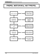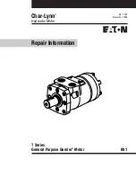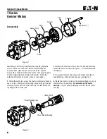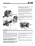
2
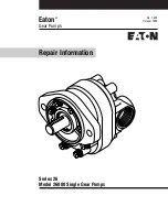
Series 26 - Model 26000 Single Gear Pumps
Introduction
Table of Contents
Introduction ................................................................................................................................
2
Identification ...............................................................................................................................
3
Tools Required ...........................................................................................................................
3
Exploded View Drawing ..............................................................................................................
4
Parts List ....................................................................................................................................
5
Disassembly ............................................................................................................................... 5 & 6
Reversibility ................................................................................................................................
7
Inspection ...................................................................................................................................
8
Reassembly ................................................................................................................................ 9 & 10
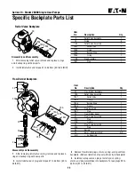
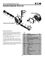
Specific Backplate Parts List ....................................................................................................... 11 &12
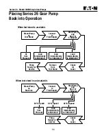
Placing Pump Back into Operation ............................................................................................. 13
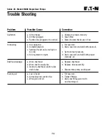
Trouble Shooting ........................................................................................................................ 14
Ordering Information .................................................................................................................. 16
Introduction
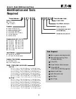
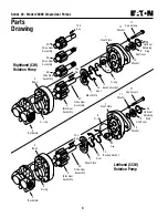
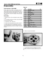
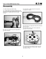
This manual provides service information for the Eaton model 26000 single gear pumps. Step by step
instructions for the complete disassembly, inspection, and reassembly of the pumps are included.
The following recommendations should be followed to insure successful repairs.
Remove the pump from the application.
Cleanliness is extremely important.
Clean the port areas thoroughly before disconnecting the hydraulic lines.
Plug the pump ports and cover the open hydraulic lines immediately after they're disconnected.
Drain the oil and clean the exterior of the pump before making repairs.
Wash all metal parts in clean solvent.
Use compressed air to dry the parts. Do not wipe them dry with paper towels or cloth.
The compressed air should be filtered and moisture free.
Always use new seals when reassembling hydraulic pumps.
For replacement parts and ordering information refer to parts list 6-634.
Lubricate the new rubber seals with a petroleum jelly (vaseline) before installation.
Torque all bolts over gasket joints, then repeat the torquing sequence to makeup for gasket
compression.
Verifying the accuracy of pump repairs on an authorized test stand is essential.
Summary of Contents for 6200D
Page 1: ...330395 Rev 01 6 02 Service Manual 6200D 330395 ...
Page 4: ...GENERAL INFORMATION 1 2 6200D 330395 8 99 ...
Page 18: ...GENERAL INFORMATION 1 16 6200D 330395 8 99 ...
Page 20: ...CHASSIS 2 2 6200D 330395 8 99 ...
Page 74: ...CHASSIS 2 56 6200D 330395 8 99 ...
Page 76: ...SWEEPING 3 2 6200D 330395 8 99 ...
Page 138: ...SWEEPING 3 64 6200D 330395 6 02 ...
Page 140: ...ELECTRICAL 4 2 6200D 330395 8 99 ...
Page 176: ...ELECTRICAL 6200D 330395 6 02 4 38 ELECTRICAL SCHEMATIC 353188 D ...
Page 177: ...ELECTRICAL 4 39 6200D 330395 6 02 WIRE HARNESSES GROUP 352986 353189 D ...
Page 178: ...ELECTRICAL 6200D 330395 6 02 4 40 WIRE HARNESSES GROUP 352986 353189 D ...
Page 179: ...ELECTRICAL 4 41 6200D 330395 6 02 WIRE HARNESSES GROUP 352986 353189 D ...
Page 180: ...ELECTRICAL 6200D 330395 6 02 4 42 WIRE HARNESSES GROUP 352986 353189 D ...
Page 181: ...ELECTRICAL 4 43 6200D 330395 6 02 WIRE HARNESSES GROUP 352986 353189 D ...
Page 182: ...ELECTRICAL 6200D 330395 6 02 4 44 WIRE HARNESSES GROUP 352986 353189 D ...
Page 184: ...HYDRAULICS 5 2 6200D 330395 8 99 ...
Page 212: ...HYDRAULICS 5 30 6200D 330395 8 99 HYDRAULIC SCHEMATIC PROPEL ...
Page 213: ...HYDRAULICS 5 31 6200D 330395 8 99 HYDRAULIC SCHEMATIC HOPPER LIFT ...
Page 214: ...HYDRAULICS 5 32 6200D 330395 6 02 OUT IN B A B A 2 3 4 5 6 1 HYDRAULIC HOSE DIAGRAM PROPEL ...
Page 215: ...HYDRAULICS 5 33 6200D 330395 6 02 HYDRAULIC HOSE DIAGRAM HOPPER LIFT ...
Page 220: ...2 2 General Purpose Motors ...
Page 227: ......
Page 228: ......
Page 229: ......
Page 230: ......
Page 248: ...ENGINE DIESEL 6 2 6200D 330395 8 99 ...

