6
6
General Purpose Motors
T Series Geroler Motors
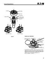
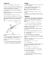
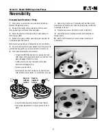
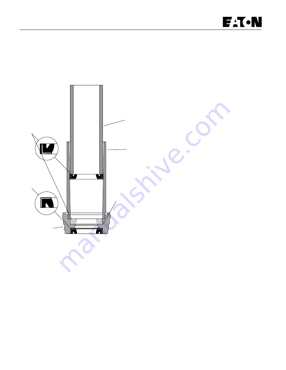
Figure 5
Important: Be sure the exclusion seal and pressure seal are
undamaged and properly seated.
12 Apply three or four drops of Loctite 277 to the threads of
the four holes in the motor housing where the mounting flange
will be attached. Apply the Loctite so that it coats the threads.
Remove all excess Loctite.
13 Install a protective sleeve or bullet over the output shaft.
Lubricate the inner edges of the exclusion and pressure seals.
Lubricate and install the 49 mm [1 15/16 in.] diameter o-ring
seal on the mounting flange. Then slide the mounting flange
down over the shaft.
14 Remove the protective sleeve and install the four cap
screws. Tighten the cap screws, in a criss-cross pattern, to 28
Nm [250 lb-in]. Be sure the output shaft does not fall out of
the housing.
11 Lubricate and install the back-up ring and pressure seal.
Use seal installation tool no. 600523 to press the pressure seal
into place (see Figure 5).
Important: The Loctite must cure completely before the
motor is put into service. Loctite curing time is six hours.
Use of Loctite Primer reduces curing time to 15 minutes.
Follow the instructions on the Loctite package.
15 Clamp the motor in the vise so the output shaft is vertical
and down. Clamp on the mounting flange.
16 Pour clean hydraulic fluid into the motor to provide start-up
lubrication.
17 Lubricate and install one of the three largest diameter seals
in the groove in the motor housing.
18 Install the drive.
Note: If the splined ends of the drive are different lengths,
install the longer end into the shaft.
Motor Timing
19 Align shaft timing dot with any bolt hole. Bolt hole will be
used for timing reference.
20 Install spacer plate, and note the position of the threaded
hole in housing aligned with the timing dot on shaft.
Important: Be sure the slots in the spacer plate provide
passage for hydraulic fluid as well as the cap screws. If the
spacer plate is flipped the motor will not operate.
21 Lightly stretch, lubricate and install the second of three
large diameter seals in the groove in the Geroler.
22 Install the Geroler.
Standard Timing Align any star point with the threaded hole
noted for the location of the timing dot (see Figure 6).
Reverse Timing Align any star valley with the threaded hole
noted for the location of the timing dot (see Figure 6).
23 Rotate the geroler to align the screw holes and install drive
spacer if applicable.
24 Lubricate and install the last one of the three large diameter
seals in the groove in the end cap.
25 Install the end cap and seven cap screws.
26 Tighten the cap screws in a criss-cross pattern, to 27-28
Nm [235-250 lb-in].
Reassembly
Mounting
Flange
Seal
Driver
Seal
Tube
Back-up Ring
(No Back-up
Ring -008)
Seal Installation Tool
Exclusion
Seal
Shaft
Pressure
Seal
Summary of Contents for 6200D
Page 1: ...330395 Rev 01 6 02 Service Manual 6200D 330395 ...
Page 4: ...GENERAL INFORMATION 1 2 6200D 330395 8 99 ...
Page 18: ...GENERAL INFORMATION 1 16 6200D 330395 8 99 ...
Page 20: ...CHASSIS 2 2 6200D 330395 8 99 ...
Page 74: ...CHASSIS 2 56 6200D 330395 8 99 ...
Page 76: ...SWEEPING 3 2 6200D 330395 8 99 ...
Page 138: ...SWEEPING 3 64 6200D 330395 6 02 ...
Page 140: ...ELECTRICAL 4 2 6200D 330395 8 99 ...
Page 176: ...ELECTRICAL 6200D 330395 6 02 4 38 ELECTRICAL SCHEMATIC 353188 D ...
Page 177: ...ELECTRICAL 4 39 6200D 330395 6 02 WIRE HARNESSES GROUP 352986 353189 D ...
Page 178: ...ELECTRICAL 6200D 330395 6 02 4 40 WIRE HARNESSES GROUP 352986 353189 D ...
Page 179: ...ELECTRICAL 4 41 6200D 330395 6 02 WIRE HARNESSES GROUP 352986 353189 D ...
Page 180: ...ELECTRICAL 6200D 330395 6 02 4 42 WIRE HARNESSES GROUP 352986 353189 D ...
Page 181: ...ELECTRICAL 4 43 6200D 330395 6 02 WIRE HARNESSES GROUP 352986 353189 D ...
Page 182: ...ELECTRICAL 6200D 330395 6 02 4 44 WIRE HARNESSES GROUP 352986 353189 D ...
Page 184: ...HYDRAULICS 5 2 6200D 330395 8 99 ...
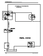
Page 212: ...HYDRAULICS 5 30 6200D 330395 8 99 HYDRAULIC SCHEMATIC PROPEL ...
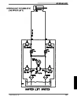
Page 213: ...HYDRAULICS 5 31 6200D 330395 8 99 HYDRAULIC SCHEMATIC HOPPER LIFT ...
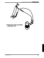
Page 214: ...HYDRAULICS 5 32 6200D 330395 6 02 OUT IN B A B A 2 3 4 5 6 1 HYDRAULIC HOSE DIAGRAM PROPEL ...
Page 215: ...HYDRAULICS 5 33 6200D 330395 6 02 HYDRAULIC HOSE DIAGRAM HOPPER LIFT ...
Page 220: ...2 2 General Purpose Motors ...
Page 227: ......
Page 228: ......
Page 229: ......
Page 230: ......
Page 248: ...ENGINE DIESEL 6 2 6200D 330395 8 99 ...

