


CF Series Portable Chiller : Air & Water-Cooled : 5 - 40 Tons
Page: 29
TEMPTEK, INC.
525 East Stop 18 Road Greenwood, Indiana 46142
317-887-6352 Fax: 317-881-1277
Email: [email protected]
gauge reading is in the normal operating range for the refrigerant type
used in the chiller.
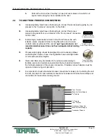
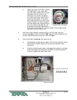
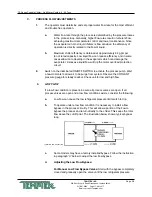
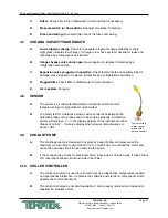
For Automatic Low Flow Bypass Valves: A “T” handle or adjusting
stem is located on the top of the valve. Turning the “T” handle or
adjusting stem in the clockwise direction puts more pressure on
the valve’s spring reducing bypass flow. Turning the “T” handle or
adjusting stem counter clockwise puts less pressure on the spring and
increases bypass flow. Adjust the “T” handle or adjusting stem until the
low pressure gauge reading is in the normal operating range for the
refrigerant type used in the chiller. If the low pressure gauge reading is
below normal, reduce the pressure on the spring to provide more bypass.
4.
HIGH FLOW
If a high flow condition is present:
a.
High flow can cause premature component wear and poor operating
conditions.
b.
Adjust the flow so that an 8°F - 10°F rise in water temperature is
indicated while the system is fully loaded.
5.
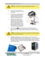
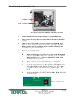
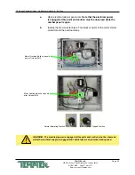
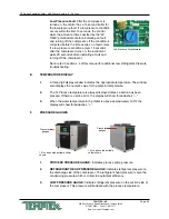
If an excessive flow situation is encountered and the motor overload circuit has
tripped, the operator must manually reset the overload relay before operations
can continue. This is done by opening the electrical panel cover and identifying
the motor overload relay.
Some overload relays have a red button that pops out if the overloads are tripper.
Simply push the button in until the overloads are reset.
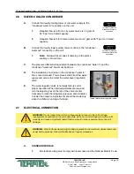
Other overload relays have a switch. This switch will be positioned with the
indicator pointing up when in normal operation. The indicator will be pointing to
the left when the overloads are tripped. To reset, simply turn the switch to where
the indicator points up.
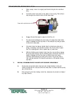
If a motor overload situation persists, the operator must adjust the flow rate to
match the system pressure loss (reduce flow rate) to prevent continual tripping of
the overload relay. This procedure is outlined here:
Automatic Low Flow
Bypass Valve
Summary of Contents for CF Series
Page 2: ......
Page 6: ...Page 6 THIS PAGE INTENTIONALLY BLANK ...
Page 22: ...Page 22 THIS PAGE INTENTIONALLY BLANK ...


