F97CMN and G97CMN: Installation, Start-up, Operating and Service and Maintenance Instructions
Manufacturer reserves the right to change, at any time, specifications and designs without notice and without obligations.
14
fit and positioning. In both upflow and downflow orientations, the
Z-pipe should NOT be resting on any sheet metal parts.
13. Secure the rubber elbow to the drain trap and the Z-pipe with spring
clamps.
14. Secure the grommet to the Z-pipe with the spring clamp.
The remaining drain line can be constructed from field supplied 1/2-in.
CPVC or 3/4-in. PVC pipe, in compliance with local building codes. A
factory-supplied 1/2-in. CPVC to 3/4-in. PVC adapter is supplied in the
loose parts bag for use as required.
15. Install the adapter or connect the 1/2-in. CPVC pipe by sliding a
spring clamp over the open end of the grommet on the outside the
furnace casing.
16. Open the spring clamp and insert the long end of the adapter or the
1/2-in. CPVC pipe into the outlet stub on the drain tube.
17. Connect additional condensate piping to a code-approved drain, or
to a condensate pump approved for use with acidic furnace
condensate and compatible with mineral and vegetable oils, such as
canola oil.
Allow at least 1/4-in. per foot (20 mm per meter) of slope down and
away from the furnace in horizontal sections of drain line.
TIP FROM CONTRACTORS:
When installing the furnace
horizontally, use the entire drain elbow (that is, do NOT cut as shown in
to connect the trap to the drain line. This helps to prevent bumps
and shocks to the drain line from damaging the furnace drain trap. Avoid
misalignment of the drain pipe which may cause kinks in the elbow.
Horizontal Orientation
1. The condensate trap outlet extends 2-in. (51 mm) below the furnace
casing. Leave enough clearance between the furnace and the
furnace platform for the trap.
2. To allow for servicing the trap, the condensate drain elbow in the
loose parts bag can be used to make a coupler to allow for future
service of the condensate trap and drain line.
3. Remove the knock-out for the condensate trap in the side of the
casing.
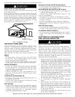
4. Install the drain trap grommet in the casing if required for
direct-vent applications. If necessary, remove the trap, install the
grommet and re-install the trap.
5. Remove the pre-formed rubber drain elbow, and two spring clamps
from the loose parts bag.
6. Connect the full or modified elbow and/or grommet to the outlet of
the condensate trap with one spring clamp. Avoid misalignment of
the drain pipe which may cause kinks in the elbow or grommet.
7. The remaining drain line can be constructed from field-supplied
1/2-in. CPVC or 3/4-in. PVC pipe, in compliance with local
building codes. A factory-supplied 1/2-in. CPVC to 3/4-in. PVC
adapter is supplied in the loose parts bag for use as required.
8. Install the adapter or connect the 1/2-in. CPVC pipe by sliding a
spring clamp over the open end of the elbow or grommet on the
outside the furnace casing.
9. Open the spring clamp and insert the long end of the adapter or the
1/2-in. CPVC pipe into the outlet stub on the drain tube.
10. Connect additional condensate piping to a code-approved drain, or
to a condensate pump approved for use with acidic furnace
condensate and compatible with mineral and vegetable oils, such as
canola oil.
Allow at least 1/4-in. per foot (20 mm per meter) of slope down and
away from the furnace in horizontal sections of drain line.
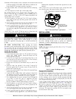
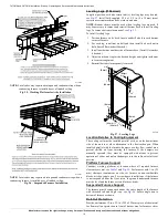
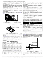
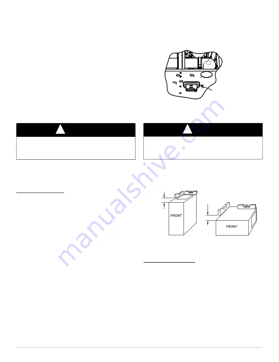
A11582
Fig. 17 – Horizontal Drain Trap Grommet
INSTALLATION
Upflow Installation
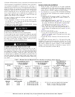
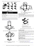
NOTE:
The furnace must be pitched as shown in
for proper
condensate drainage.
A11237
Fig. 18 – Furnace Pitch Requirements
Supply Air Connections
For a furnace not equipped with a cooling coil, the outlet duct shall be
provided with a removable access panel. This opening shall be
accessible when the furnace is installed and shall be of such a size that
the heat exchanger can be viewed for possible openings using light
assistance or a probe can be inserted for sampling the air stream. The
cover attachment shall prevent leaks.
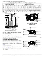
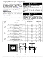
Connect supply-air duct to flanges on furnace supply-air outlet. Bend
flange upward to 90° with wide duct pliers, see
. The supply-air
duct must be connected to ONLY the furnace supply-outlet-air duct
flanges or air conditioning coil casing (when used). DO NOT cut main
furnace casing side to attach supply air duct, humidifier, or other
accessories. All supply-side accessories MUST be connected to duct
external to furnace main casing.
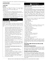
NOTICE
!
The field-supplied, accessory horizontal drain trap grommet is ONLY
REQUIRED FOR DIRECT VENT APPLICATIONS. It is NOT
required for applications using single-pipe or ventilated combustion air
venting.
NOTICE
!
This furnace is certified to leak 2% or less of nominal air conditioning
CFM delivered when pressurized to 1-in. water column with all present
air inlets, including bottom closure in upflow and horizontal
applications, air outlets, and plumbing and electrical ports sealed.
Remove knockout.
Install grommet before
relocating condensate
trap.
NOTE: Trap grommet is required only for direct-vent
applications.
LEVEL 0-IN. (0 MM) TO
1/2-IN. (13 MM) MAX
UPFLOW OR
DOWNFLOW
HORIZONTAL
MIN 1/4-IN. (6 MM) TO
1/2-IN. (13 MM) MAX


