Tempco TEC-9200 User Manual Download Page 3

1. Introduction

TEC-9200 Fuzzy Logic plus PID microprocessor-based controller incorporates a bright, easy to read, 4-digit LED display which indicates
the process value. Fuzzy Logic technology enables a process to reach a predetermined set point in the shortest time, with the minimum
of overshoot during power-up or external load disturbance. The units are housed in a 1/16 DIN case, measuring 48mm x 48mm with
75mm behind-panel depth. The units feature three touch keys to select the various control and input parameters. Using a unique function,
you can determine which parameters are accessible by the user. You can also put up to five parameters at the front of the user menu by
using SEL1 to SEL5 found in the setup menu. These are particularly useful to OEM's as it is easy to limit access and configure the menu
to suit the specific application.

TEC-9200 is powered by 20–32 or 90–264VAC supply, incorporating a 3 amp control relay output and dual 3 amp alarm relay outputs as
standard with a second alarm that can be configured in the second output for cooling purposes or as a dwell timer. Alternative output options
include SSR drive, triac, 4–20mA and 0–10 volts. TEC-9200 is fully programmable for PT100, thermocouple types J, K, T, E, B, R, S, N,
0–20mA, 4–20mA, and voltage signal input, with no need to modify the unit.

Digital communications format RS-485 or 4–20mA retransmission are available as an additional option. These options allow the TEC-
9200 to be integrated with supervisory control systems and software, or alternatively to drive remote displays, chart recorders, or data
loggers.

For nearly a hundred years, PID control has been used and has proven to be an efficient controlling method by many industries, yet
PID has difficulty dealing with some sophisticated systems such as second and higher order systems, long time-lag systems, during set
point changes and/or load disturbances, etc. The PID principle is based on a mathematical model which is obtained by tuning the
process. Unfortunately, many systems are too complex to describe precisely in numerical terms. In addition, these systems may vary
from time to time. In order to overcome the imperfections of PID control, Fuzzy Technology was introduced. What is Fuzzy Control? It
works like a good driver. Under different speeds and circumstances, he can control a car well based on previous experience, and does
not require knowledge of the kinetic theory of motion. Fuzzy Logic is a linguistic control which is different from numerical PID control. It
controls the system by experience and does not need to simulate the system precisely as a PID controller would.

The function of Fuzzy Logic is to adjust PID parameters internally in order to make manipulation of output value MV more flexible and
adaptive to various processes.

The Fuzzy Rule may work like this:
If the temperature difference is large, and the temperature rate is large, then 

MV is large.

If the temperature difference is large, and the temperature rate is small, then 

MV is small.

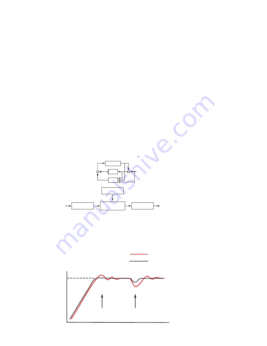
PID+Fuzzy Control has been proven to be an efficient method to improve control stability as shown by the comparison curves below:

3

PROCESS

PID

FUZZY

MV

PV

_

+

SV

+

+

Fuzzy Rule

Fuzzy Inference
Engine

Defuzzifier

Fuzzifier

Digital

information

Language

information

Digital
information

Figure 1.1
 Fuzzy PID System Block

Figure 1.1
 Fuzzy PID System Block

PID + FUZZY CONTROL

Warm Up

Load Disturbance

PID control with properly tuned

PID + Fuzzy control

Set point

Temperature

Time

Figure 1.2 Fuzzy PID
Enhances Control 
Stability

Figure 1.2 Fuzzy PID
Enhances Control 
Stability

Summary of Contents for TEC-9200

Page 1: ...ure Controller TEMPCO Electric Heater Corporation 607 N Central Avenue Wood Dale IL 60191 1452 USA Tel 630 350 2252 800 323 6859 Fax 630 350 0232 website http www tempco com Copyright 2003 Tempco Elec...

Page 2: ...nderstood and met CONTENTS 1 Introduction 2 Numbering System 3 Specifications 4 Installation 5 Operation 6 Recalibration 7 Error Messages and Diagnosis Information in this user s manual is subject to...

Page 3: ...lling method by many industries yet PID has difficulty dealing with some sophisticated systems such as second and higher order systems long time lag systems during set point changes and or load distur...

Page 4: ...gurable 9 Other 4 Control Mode 3 Field configurable 9 Other 5 Output 1 0 None 1 Relay 3A 240VAC 2 Pulse DC for SSR drive 24VDC 20mA max 3 4 20mA linear max load 500 ohms 4 0 20mA linear max load 500 o...

Page 5: ...rotection NEMA 4X IP65 EMC emission EN50081 1 EN55011 EMC immunity IEC801 2 IEC801 3 IEC801 4 Sensor Input Type Range F Accuracy F Range C Accuracy C J Iron Constantan 58 to 1832 F 3 6 F 50 to 1000 C...

Page 6: ...ure Do not use this instrument in areas under hazardous conditions such as excessive shock vibration dirt moisture corrosive gases or oil The ambient temperature of the areas should not exceed the max...

Page 7: ...minals should not be used as jumper points as they may be internally connected causing damage to the unit Verify that the ratings of the output devices and the inputs are not exceeded Electrical power...

Page 8: ...length Table 4 1 International Thermocouple Cable Color Codes Color of overall sheath Output Wiring There are several types of output modules see section 2 that can be selected for output 1 when order...

Page 9: ...the value of the selected digit or to change the selection for an index parameter Selects the parameter in a direct sequence Also used to select the tool program parameters Selects the parameters in h...

Page 10: ...UE SET POINT VALUE SHIF PB TI TD AhY1 AhY2 hYST ADDR LO SC hI SC PL 1 PL 2 INPT UNIT RESO CON A A1 MD A1 SF A2 MD A2 SF CYC CCYC C PB D B Security Level 1 Security Level 2 Short scroll advances forwar...

Page 11: ...e selected input 999 F PL 1 Power limit of Output 1 0 100 100 PL 2 Power limit of Output 2 0 100 100 INPT Input type selection J K T E B R S or N TC J K T E B R S or N type T C PT100 DIN PTDN PT100 JI...

Page 12: ...the Drift compensation code FAIL SAFE Fail Safe Defines the status of the outputs if the sensor fails OUT 1 ALM 1 ALM 2 or or or OUT 2 or Select the status for Output 1 ON or OFF Select the status fo...

Page 13: ...minutes The dwell timer starts counting when the process value reaches the set point value See sections 5 10 and 5 13 for more details RAMP Ramp Rate This controls the heating or cooling rate of the...

Page 14: ...cimal points Note that 2 dP can only be used for linear process input when Pu is selected for UNIT CON A Control Action of Output 1 This selects reverse heating action or direct cooling action for out...

Page 15: ...e lower display For example if you select LOCK for LEV 2 and press the scroll key for 3 2 seconds to enter the selection the all parameters in level 2 can no longer be changed A LOCK message will appe...

Page 16: ...values for the process which are then automatically entered into the nonvolatile memory During the second period of the auto tune program the controller performs PID control to verify the results and...

Page 17: ...Sequence Symptom Solution Proportional Band P PB Slow response Decrease PB High overshoot or oscillations Increase PB Integral Time I TI Slow response Decrease TI Instability or oscillations Increase...

Page 18: ...ble value When using on off control the parameters TI TD and CYC will have no effect on the system and both manual mode and the auto tune program will be disabled 5 9 Cooling Control Cooling control o...

Page 19: ...d Hold Alarm A1SF LT HO When selected in any alarm mode prevents an alarm on power up The alarm is enabled when the process value reaches the set point value Thereafter the alarm acts as a latch alarm...

Page 20: ...the controller fails Manual control mode is an open loop control The process may rise to a dangerous temperature Special attention must be paid to the process in order to prevent damage to the system...

Page 21: ...being open on initial start up The timer begins to count down once the set point temperature has been reached After the amount of time set in ASP1 has elapsed the alarm 1 relay will close This functi...

Page 22: ...libration data will be lost Do not attempt recalibration unless you have the appropriate calibration equipment available If the calibration data is lost you will need to return the controller to your...

Page 23: ...e display Now the display will indicate process value with respect to the INPT type selected Feed a standard signal to the appropriate input terminals and examine the accuracy of the display 4 Press t...

Page 24: ...en or shorted heater circuit Open coil in external contactor Burned out line fuses Burned out relay inside control Defective solid state relays Defective line switches Burned out contactor Defective c...

Page 25: ...d into EEPROM Replace EEPROM 11 Process display shows OVER Overflow error data out of range during execution of software program Check for electrical noise 12 Process display shows LOCK Attempt to cha...

Page 26: ...ic Heater Corporation 607 N Central Avenue Wood Dale IL 60191 1452 USA Tel 630 350 2252 800 323 6859 Fax 630 350 0232 website http www tempco com Copyright 2003 Tempco Electric Heater Corporation all...

Reviews: