background image

FC-3800 Facility and Installation Guide                                                                  Section 3: Unpacking and Installation

0101-8604-0, Rev. F

3-15

FC-3800 F & I Guide

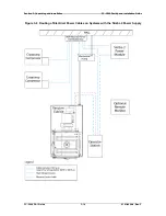
Figure 3-9  Routing of EMO Cables and Copper Straps

                      on Systems with the Simba 2 Power Supply

Summary of Contents for FC-3800

Page 1: ...D INSTALLATION GUIDE FOR FC 3800 EVAPORATION SYSTEMS Temescal a division of Ferrotec USA Corporation 4569 C Las Positas Road Livermore CA 94551 Tel 1 800 522 1215 Fax 925 449 4096 0101 8604 0 Revision F March 2011 ...

Page 2: ...tions 1 4 2 2 1 and 3 2 7 Modified Figures 3 4 through 3 14 Clarified specifications and instructions regarding water supplies 2 and 3 Nov 2006 SS E In sections 1 4 and 2 5 corrected values for power drops to be provided for vacuum system and e beam power supplies Added Figure 2 3 and updated Figure 3 2 Deleted former Figures 3 7 3 9 and 3 11 Corrections provided by Temescal Field Service and Teme...

Page 3: ...m Grounding Requirements 2 4 2 2 Vacuum Cubicle Grounding for Simba 2 Power Supply 2 5 2 3 Low Z Grounding Requirements on Systems with a CV 6SLX or CV 12SLX Power Supply 2 6 3 1 Elevation View of Vacuum Cubicle Showing Vacuum Cubicle Height 3 7 3 2 System Plan View Showing Dimensions of Main System Components 3 8 3 3 Utility Connection Points on Rear of Vacuum Cubicle 3 9 3 4 Routing of Customer ...

Page 4: ...FC 3800 F I Guide ii 0101 8604 0 Rev F This page intentionally left blank for pagination purposes ...

Page 5: ... local electrical codes Refer to the power supply portion of the documentation to determine the proper electrical ground for high voltage components 6 Before servicing any high voltage component switch off the electrical power at the component s main power switch This switch should have a lockout feature Lock the power off and keep the key with you while you are working on the equipment 7 Certain ...

Page 6: ...vacuum system and the high voltage power supply Screens protecting extra high voltage conductors should be removed only if appropriate action has been taken to ensure that extra high voltage conductors are dead and cannot be reenergized inadvertently In addition all personnel should be aware of 1 The Electricity Factories Act Special Regulations 1908 and 1944 in particular Regulations 18 d and 28 ...

Page 7: ... etc 2 Do not expose the vent and purge valves to excessive pressures The nitrogen line regulator is factory set at 15 psi and must not be adjusted above 20 psi 3 Prevent oil grease water sweat etc from getting into the vacuum chamber 4 Replace the source tray shield correctly to ensure that the ceramic parts or the high voltage feedthroughs are protected from being coated 5 Clean all mechanical p...

Page 8: ... Safety Data Sheet s covering the evaporant s in question c Certain powders titanium for instance can cause flash fires when exposed to oxygen or other oxidizers Therefore when opening the chamber door after a deposition cycle exercise extreme caution and allow time for the coating surface to oxidize Breakage of some of the more reactive condensates may be hazardous even when the above precautions...

Page 9: ...s in this manual YES NO If YES typographical or technical please cite the pages ____________________________________________________________________ 4 How important was this F I Guide in preparing for your system circle one Essential Important Nice to Have Not Important 5 Do you currently own and operate any other Temescal Systems YES NO please specify _____________________________________________...

Page 10: ...FC 3800 F I Guide viii 0101 8604 0 Rev F This page has been intentionally left blank for pagination purposes ...

Page 11: ...npacking and Installation 1 1 2 In This Section This remainder of this section covers the following topics 1 2 Temescal Contact Information 1 3 General Safety Information 1 4 Site Preparation Checklist 1 2 Temescal Contact Information If you have any questions or concerns or if you need assistance contact us at one of the following telephone numbers To schedule an installation or a field service v...

Page 12: ...WARNINGS AND COMPLY WITH THEIR GUIDELINES 1 4 Site Preparation Checklist The customer is responsible for providing properly rated power water air and gases services to their appropriate termination points at the System prior to installation Specific requirements and installation specifications required for each system are detailed in this Facilities and Installation F I Guide The customer is also ...

Page 13: ...Cubicle 100 psig 6 89 bar maximum inlet pressure 50 psig 3 45 bar minimum delta pressure 50º 70º F 10º 21º C maximum inlet temperature Filtered to 50 microns Flow Rate Requirements Chamber walls and doors 6 0 gpm 22 7 L min Each e beam source 2 75 to 5 0 gpm 10 4 to 18 9 L min 5 cm ion beam source 0 5 gpm 1 9 L min Each crystal monitor 0 5 gpm 1 9 L min Cold Water Supply 2 Cryopump Compressors Min...

Page 14: ...well as DC For illustrations and additional details see section 2 4 Main System Drop 1 208 VAC 60 Hz 3 phase 4 wire 150 A or 400 VAC 50 Hz 3 phase 4 wire 90 A HV Power Supply Drop 2 Select one power supply only Simba 2 208 240 VAC 50 60 Hz 3 phase delta 4 wire 90 A Simba 2 380 VAC 50 60 Hz 3 phase delta 60 A current Simba 2 480 VAC 50 60 Hz 3 phase delta 50 A CV 6SLX 208 VAC 50 60 Hz 3 phase 4 wir...

Page 15: ...Relative Humidity 50 maximum must be free of corrosive fumes and vapors Air Conditioning Capable of 5 kW cooling 2 2 Water Both cold and hot water must be filtered to 50 microns In addition the water supplied to the system must have a ph level of between 6 0 and 8 0 To prevent hard water deposits it must be conditioned to maintain a calcium carbonate CaCo3 content of less than 75 ppm Actual water ...

Page 16: ...inimize pressure fluctuations in the system a vent gas supply pressure of 60 to 120 psig is recommended The actual venting pressure within the system is lower The FC 3800 system features built in regulation to reduce this pressure as required 2 3 2 Pneumatic Air oil free for activation of valves 90 to 120 psig 6 21 to 8 27 bar 2 3 3 Helium One bottle 99 999 pure For additional details see section ...

Page 17: ...volt ohm meter The maximum allowable resistance is 3 ohms If the resistance is greater than that value pouring salt water or copper sulfate down the sides of the rods may lower the resistance to the required level To ensure a low impedance path to ground the rods must be connected to each other and to the vacuum chamber by a length of 3 inch 76 mm wide copper strap For runs of less than 60 feet 18...

Page 18: ...Section 2 Facility Requirements FC 3800 Facility and Installation Guide FC 3800 F I Guide 2 4 0101 8604 0 Rev F Figure 2 1 Facility and System Grounding Requirements ...

Page 19: ...grounding point as indicated in Figure 2 2 Alternatively a short length of copper strap can be used to connect grounding lug on the gun interface to the grounding bracket on the Simba 2 power module as indicated in Figure 3 9 If the gun interface is mounted in the operator station its low impedance ground is provided by the length of copper strap that connects the operator station to the system s ...

Page 20: ...nd the surface on which it is mounted usually the upper surface of the source tray must be clean and free of evaporated material The mounting surface must be made of nonmagnetic material The source must be securely bolted to the mounting surface 2 5 4 Grounding Hooks One grounding hook is provided at each of the following locations of the system where high voltage may be present Inside the vacuum ...

Page 21: ...in good condition and properly packed It is essential to all concerned that the contents of the shipment be examined carefully when it is unpacked to make sure that no damage has occurred in transit First check the materials received against the packing list to be certain that all elements are accounted for Then check each component for damage Normally the major components of the system as shipped...

Page 22: ...ply power to the system Instead call for a Temescal service representative to make the service connections approve the installation energize the system and demonstrate that it performs as designed 3 2 1 Equipment and Personnel Required The following types of workers with their tools will be required to install the system 1 Mechanical technicians or movers will remove any bracing and shipping hardw...

Page 23: ...nobstructed fashion 3 2 4 Installing the Power Distribution Box The power distribution box is normally mounted on a nearby wall To ensure unobstructed access as cables are being fed through the bottom of the box It should be mounted at least 12 inches 305 mm above any obstructions The recommended distance from the floor to the bottom of the box is 32 inches 815 mm On systems supplied with 208 V ac...

Page 24: ...lower if this option is included in your system and install and connect the roughing line and the mechanical pump exhaust To do so 1 Loosen the clamps connecting the flexible hose to the mechanical pump 2 Release the bolts that hold the mechanical pump to the system frame during shipment allowing the pump to rest on the floor 3 Retighten the clamps on the flexible hose to isolate the vacuum cubicl...

Page 25: ...d to a maximum of 15 psig 1 03 torr prior to shipment in accordance with U S Federal Aviation Agency regulations During the installation of any such Temescal system the Temescal service representative will be responsible for recharging and decontaminating the Helium lines and the cryopumps Thereafter the customer will be responsible for maintaining the integrity of the system In such cases the cry...

Page 26: ... cables and lines per code However all electrical connections between the power distribution box and the vacuum cubicle the operator station the mechanical pump s and the power supplies shall be made by or under the supervision of the Temescal service representative Once all connections have been properly made the Temescal service representative is responsible for energizing the system or for supe...

Page 27: ...of customer supplied cables and plumbing lines Figure 3 6 Routing of lines supplying helium to cryopump compressors Figures 3 7 through 3 12 Routing of electrical and data cables between major system components on systems equipped with a Simba 2 e beam power supply Figures 3 13 and 3 14 Routing of electrical and data cables between major system components on systems equipped with either the CV 6SL...

Page 28: ...g and Installation FC 3800 Facility and Installation Guide FC 3800 F I Guide 3 8 0101 8604 0 Rev F Figure 3 2 System Plan View Showing Dimensions of Main System Components System Shown with Optional Simba 2 Power Supply ...

Page 29: ...FC 3800 Facility and Installation Guide Section 3 Unpacking and Installation 0101 8604 0 Rev F 3 9 FC 3800 F I Guide Figure 3 3 Utility Connection Points on Rear of Vacuum Cubicle ...

Page 30: ...Section 3 Unpacking and Installation FC 3800 Facility and Installation Guide FC 3800 F I Guide 3 10 0101 8604 0 Rev F Figure 3 4 Routing of Customer Supplied Service Lines in 208 V Installations ...

Page 31: ...FC 3800 Facility and Installation Guide Section 3 Unpacking and Installation 0101 8604 0 Rev F 3 11 FC 3800 F I Guide Figure 3 5 Routing of Customer Supplied Service Lines in 400 V Installations ...

Page 32: ...Section 3 Unpacking and Installation FC 3800 Facility and Installation Guide FC 3800 F I Guide 3 12 0101 8604 0 Rev F Figure 3 6 Routing of Temescal Supplied Helium Lines to Cryopump Compressors ...

Page 33: ...FC 3800 Facility and Installation Guide Section 3 Unpacking and Installation 0101 8604 0 Rev F 3 13 FC 3800 F I Guide Figure 3 7 Routing of Control Data Cables on Systems with the Simba 2 Power Supply ...

Page 34: ...ection 3 Unpacking and Installation FC 3800 Facility and Installation Guide FC 3800 F I Guide 3 14 0101 8604 0 Rev F Figure 3 8 Routing of Electrical Power Cables on Systems with the Simba 2 Power Supply ...

Page 35: ...800 Facility and Installation Guide Section 3 Unpacking and Installation 0101 8604 0 Rev F 3 15 FC 3800 F I Guide Figure 3 9 Routing of EMO Cables and Copper Straps on Systems with the Simba 2 Power Supply ...

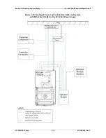
Page 36: ...ing and Installation FC 3800 Facility and Installation Guide FC 3800 F I Guide 3 16 0101 8604 0 Rev F Figure 3 10 Routing of Power and Control Data Cables on Systems with Either the CV 6SLX or the CV 12SLX Power Supply ...

Page 37: ...Installation Guide Section 3 Unpacking and Installation 0101 8604 0 Rev F 3 17 FC 3800 F I Guide Figure 3 11 Routing of EMO Cables and Copper Grounding Straps on Systems with Either the CV 6SLX or the CV 12SLX Power Supply ...

Page 38: ...Section 3 Unpacking and Installation FC 3800 Facility and Installation Guide FC 3800 F I Guide 3 18 0101 8604 0 Rev F ...

Reviews: