


AZ3s USER MANUAL
ST.TEC.054
56 / 60
7.2.
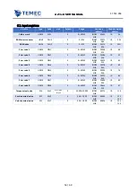
Diagnostic
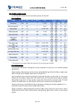
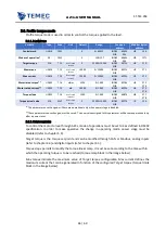
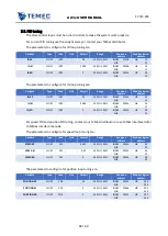
Errors are diagnosed through led and through drive parameters.
The following table summarizes the possible errors with the corresponding code and with the
corresponding LED colour:
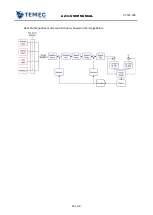
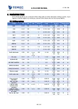
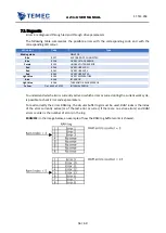
To understand which error is currently active or which errors occurred during the current work cycle,
is possible to check Error code x parameters.
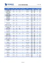
To read correctly the errors RAM log, the circular buffer logic must be used. RAM index is the index
of the error currently active (or of the last error occurred, if there are no active errors) and RAM
errors counter is the number of errors in the log.
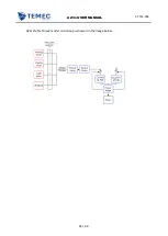
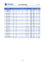
EXAMPLE: In the image below, an example of how the RAM log buffer works is showed.
LED colour
Code
Type
Blinking white
-
DRIVE OK
Blue
8257
ENCODER NOT CONNECTED
Blue
8258
OVER VOLTAGE ERROR
Purple
8259
UNDER VOLTAGE ERROR
Red
8260
OVER CURRENT U
Red
8261
OVER CURRENT V
Red
8262
OVER CURRENT W
Light blue
8263
OVER TEMPERATURE
Blue
8264
I2T ERROR
Light blue
8266
THERMISTOR ALARM ERROR
Yellow
Da 16449 a 24732
INTERNAL ERROR


