


AZ
2
USER MANUAL
ST.TEC.003.EN Rev. 2.1
33 / 52
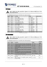
6.4.1.
A
DVANCED PARAMETERS
!
Read carefully the safety precautions reported in 1.6 before modifying any of the
advanced parameters!
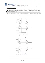
The figure below represents the real voltage waveform imposed on the motors during the normal
run:
Figure 17: real ramp waveform in synchronous mode
It is different to the one in Figure 8 to obtain a better stop precision, following these steps (for each
motor):
the drive calculates the motor speed when it applies the max voltage;
from the speed and the deceleration time, the drive calculates how many pulses before the
limit it must start the ramp (point A), using the following expression:
o
close ramps
deceleration start pulses motor 1 =
S100
– (speed *
M102
/ 2 + ( speed *
M102
/ 2 ) / 2
SG05
)
o
open ramps
deceleration start pulses motor 1 =
S102
– (speed *
M105
/ 2 + ( speed *
M105
/ 2 ) / 2
SG05
)
when the decelerating ramp reaches the approaching voltage the output voltage is
maintained constant;
S118
(
S218
for motor 2) pulses before the limit, the drive short-circuit the motor terminals
(point B) at least for
S120
(
S220
for motor 2) ms.


