background image

30

Temco DV5200 Series

78674

WARNING: Failure to position the parts in accor-
dance with these diagrams or failure to use only 
parts specifically approved with this heater may 
result in property damage or personal injury.

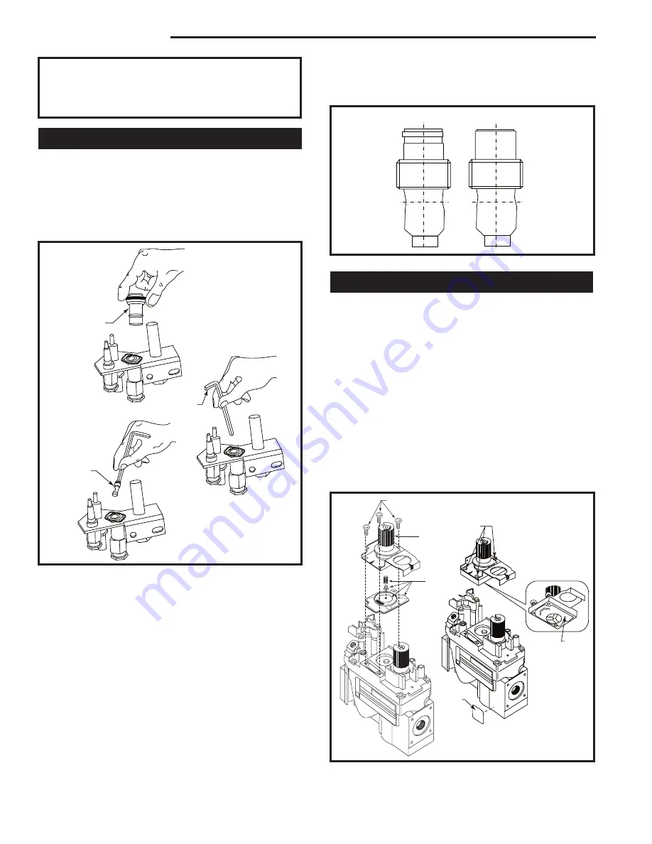
Replace Pilot Orifice

1.  The pilot hood is held in place by spring pressure. 

Remove the hood by pulling it directly up from the 
pilot bracket. (Fig. 42)

2.  Insert a 3/32” (4 mm) Allen wrench into the hexago-

nal keyway of the injector and rotate it counterclock-
wise until it is free of the injector journal. (Fig. 42)

T207

remove pilot hood

1/8/04   djt

Pilot Hood

Allen 

Wrench

Conversion 

Pilot

T207

Fig. 42

  Remove pilot hood and orifice. Insert conversion 

orifice.

3.  Verify the new injector is proper for the applica-

tion. The injector size is stamped on the side of the 
injector near the top. LPG injectors have a groove 
machined around their circumference near the top, 
while the NG injectors do not have a groove. (Fig. 
43) Install the conversion orifice furnished with unit 
(Conversion Kit).

4.  Insert the Allen wrench into the end of the injector. 

Insert the injector into injector journal, and rotate 
the injector clockwise until a torque of 9 in/lbs. Is 
achieved. Replace the pilot hood by aligning the tab 
n the base of the hood with the slot in the side of the 
pilot journal. Push the hood down, directly onto the 

pilot bracket. (Fig. 43) The hood must sit squarely on 
the bracket for proper operation. Check to insure the 
hood is properly seated onto the pilot bracket.

T208

conversion 

injectors

1/8/04  djt

LPG

NG

T208

Fig. 43 

 Injectors.

Convert Valve to LP

1.  Using a Torx T20 bit or slotted screwdriver, remove 

and discard the three (3) pressure regulator mount-
ing screws (A), pressure regulator tower (B) and 
diaphragm (C). (Fig. 44)

2.  Insure the rubber gasket (D) is properly positioned 

and install the new HI/LO pressure regulator assem-
bly to the valve using the new screws (E) supplied 
with the kit. Tighten screws securely. (Fig. 44)

3.   Install the enclosed installation label (F) to the valve 

body where it can easily be seen.

4.  Apply gas to system and relight appliance according 

to manufacturer’s instructions.

5.  With the main burner “ON”, test the new pressure 

regulator assembly for leaks using a soap solution.

FC107

SIT820

valve conversion

10/03   

A

B

C

OFF

PILO

T

ON

D

E

F

FC108

SIT

regulator

conversion

10/03

OFF

PILOT

ON

FC1007/108

Fig. 44

  Remove mounting screws, pressure regulator tower 

and diaphragm assebly, discard. Replace regulator.

Summary of Contents for DV5200MB

Page 1: ... Follow the gas suppliers instructions If you cannot reach your gas supplier call the fire department DO NOT STORE OR USE GASO LINE OR OTHER FLAMMABLE VAPORS AND LIQUIDS IN THE VICINITY OF THIS OR ANY OTH ER APPLIANCE WARNING Improper installation ad justment alteration service or main tenance can cause injury or property damage Refer to this manual For assistance or additional information consult ...

Page 2: ...round Material 7 Gas Specifications 8 Gas Inlet and Manifold Pressures 8 Gas Line Installation 8 General Venting Information General Venting 9 General Venting Information Termination Location 10 Termination Clearances 11 Sidewall General Venting Information 12 Flex Venting 12 Sidewall Horizontal Venting 13 Flex Vent Offsets 13 Flex Vent Through the Roof Vertical Applications 15 VSK7MH Vertical Flex...

Page 3: ...me odor the first time it is burned This is due to the manufacturing process Please ensure that your room is well ventilated open all windows It is recommended that you burn your fireplace for at least four 4 hours the first time you use it If the op tional fan kit has been installed place the fan switch in the OFF position during this time WARNING Check with your electronics manufac turer before ins...

Page 4: ...nal for the horizontally vented gas fueled heating appliance or equipment The sign shall read in print size no less than one half 1 2 inch in size GAS VENT DIRECTLY BELOW KEEP CLEAR OF ALL OBSTRUCTIONS Inspection The state or local gas inspector of the side wall horizontally vented gas fueled equipment shall not approve the installation unless upon inspection the inspector observes carbon monoxide...

Page 5: ... 1 Fireplace specifications and framing dimensions NOTE Flex pipe dimaeters are 4 for inner pipe and 7 for outer pipe Bottom Gas Line Access Gas Line Access Gas Line Access J Box Access J Box Access Ref DV5200MBN A 35 908 mm B 33 838 mm C 32 832 mm D 34 876 mm E 21 543 mm F 6 159 mm G 33 838 mm H 34 870 mm I 19 489 mm J 13 340 mm K 1 16 mm L 5 143 mm M 5 140 mm N 4 114 mm O 3 76 mm P 73 1867 mm Q 5...

Page 6: ...applicable insulation codes Drywall should be installed around the unit to prevent insulation from contacting the body Note Never allow the vapor barrier to contact the outer case of this fireplace or venting 5 Drywall can be extended flush on the bottom top and to the outermost part of the sides of the fire place 6 If you are installing the top vent unit with a 90 elbow installed the minimum clearan...

Page 7: ...ts must not be placed on a noncombustible mantel unless the noncombustible mantel meets the minimum height and width require ments for a combustible mantel Surround Material When using materials around the face of the fireplace these materials must be suitable to withstand the tem peratures which they will encounter Also these materi als must not extend out in front of the face of the unit in effec...

Page 8: ...minimum of 3 8 iron pipe with a gas supply pressure of 4 5 w c from the gas meter Consult with local gas utility and ANSI223 1 NFPA 54 if any questions arise concerning pipe sizes 6 Turn the gas supply to ON and check for leaks DO NOT USE OPEN FLAME FOR THIS PURPOSE Use an approved leak testing solution 7 The appliance and its appliance main gas valve must be disconnected from the gas supply pipin...

Page 9: ...th local codes or in the absence of same with CSA B149 1 installation codes in Canada or the current National Fuel Gas Code ANSI Z223 1 NFPA 54 in the USA regarding special vent termination clearances These fireplaces are certified for use with four types of venting systems 1 Temco 4 x 7 dia flex vent 2 Temco TDV series 4 x 7 dia rigid vent 3 Simpson Dura Vent GS series 4 x 6 dia vent Review general ...

Page 10: ...r assembly 4 6 m above the meter regulator assy I Clearance to service regulator vent outlet 3 91 cm 3 91 cm J Clearance to nonmechanical air supply inlet 6 15 cm for appliances 10 000 6 15 cm for appliances to building or the combustion air inlet to any Btuh 3kW 12 30 cm for 10 000 Btuh 3kW 9 other appliances appliances 10 000 Btuh 3kW and 23 cm for appliances 10 000 100 000 Btuh 30kW 36 91 cm Bt...

Page 11: ...cation Combustible 6 152mm Noncombustible 2 50mm C D C E V V Combustible Noncombustible V V V 584 15 Fig 10 Termination clearances NOTE Use only venting systems and components as certified with the appliance Use of uncertified vent systems or components will void the warranty and may compromise the operation of the fireplace its systems and components as certified with the appliance 2 51mm 1 25mm 1 25...

Page 12: ...gement by using chart above and deducting 3 914 mm from the maximum horizontal distance for the second 90 elbow VO584 100 Vent Opening 2 99 djt Vent Opening for Combustible Wall 9 248 mm 10 273 mm 5 149 mm 4 124 mm Fireplace Hearth Framing Detail Opening for Noncombustible Wall Rnd 8 Dia 203 mm Min Fireplace Hearth VO584 100 Fig 15 Locate vent opening on wall 33 838 mm Minimum 53 1346 mm Maximum 2...

Page 13: ...or HFTK kit terminal beyond the brick surface If the BEF extension is used measure to the outside surface of the framed wall and add 4 additional inches to the venting length T185 spacer springs 12 3 03 djt Flex Outer Vent Spacer Springs Flex Flue T185 Fig 17 Wrap spacer spring around flex flue pipe overlapping ends CAUTION Care must be taken when tight ening clamps so the flex does not tear at clamp...

Page 14: ...ter pipe on cap Step 4 Slide 7 outer flex over inlet and secure with band clamp 5 Secure vent cap terminal to exterior wall with screw type fasteners as needed Fig 21 6 Connect corrugated side of the extension collar 7 dia into the 7 dia flex pipe Fig 22 Place a small bead of silicone around the collar approximately 1 4 from the leading edge of the corrugation Insert the collar firmly into the flex pi...

Page 15: ...n Shield T190 Fig 24 Attic insulation shield 6 1 8m Maximum 35 10 7m Maximum T191 thru the roof installation 12 5 03 djt Roof Attic Insulation Shield 7 178 mm Dia Joists T191 Fig 25 Typical through the roof installation The VSK7MH 2 Kit contains Vertical Termination Cap and Storm Collar 4 7 dia x 24 Rigid Pipe unitized 7 dia Roof Support Components 10 Length of 4 x 7 Aluminum Flex Vent w Clamps Ad...

Page 16: ...shall not be recessed into a wall or sid ing The vent system shall be properly supported so there are no sags in the system Supports must be used at least every 3 914mm on horizontal section and every 6 1 8m on vertical Horizontal sections must maintain a minimum 1 4 rise per linear foot of horizontal run Combustible clearances from any horizontal vent pipe area must be 2 51mm from top of vent and...

Page 17: ...ncertified vent systems or components will void the warranty and may compromise the operation of the fireplace its systems and components as certified with the appliance Use of uncertified vent systems or components will void the warranty and may compromise the operation of the fireplace Through the Roof Vertical Venting When the venting penetrates a roof the system must be insalled in accordance with ...

Page 18: ... necessary to replace the last vent section with a shorter vent section In addition you may also mea sure the distance between the wall and back flanges of the terminal base plate Next trim off the terminal flue and inlet pipes to the dimension measured and reinstall the vent terminal A A A T197 short vent terminal 12 8 03 djt Inlet Pipe Wall Thimble HSQ47 Vent Terminal Cut Lines Push vent terminal ...

Page 19: ... uses 7 4 Flex HFTK Round Hor Term Cap High Wind Includes 7 4 Flex x 3 ft long CDV HSK Round Hor Term Cap uses 7 4 Flex RN47 Vertical Vent Kit Includes 7 4 flex x 10 ft long Firestop Thimble Assy VSK7MH 2 Vertical Vent Kit uses 7 4 Flex VSK7 T199 T204 TDV Series Direct Vent System Installation TDV45S Elbow TDV90 Elbow HSQ47 Horizontal Vent terminal Includes Wall thiumble 75915 SC7 Storm Collar 7605...

Page 20: ...hing the upper door latches will be less visible once the upper louvre is installed 7 Reinstall the upper and lower louvre assemblies Refer to louvre installation Glass Cleaning It will be necessary to clean the glass periodically Dur ing start up condensation which is normal forms on the inside of the glass and causes dust lint etc to cling to the glass surface Also initial paint curing can de po...

Page 21: ... Refer to Glass Door Removal Procedure 2 Remove logs from carton and inspect 3 Rear log should be installed onto rear log supports Match up slots on rear of log with the vertical log bracket tabs 4 The front log should be placed on the center log sup ports slots aligned with tabs and log placed rear ward 5 Top twigs can then be placed in their designated po sitions provided with pins on back logs ...

Page 22: ...IT Valve and pilot HI L O OFF ON O F F P I L O T O F F E A PILOT THTP TP TH Pilot Screw Wall Switch not supplied Thermopile Pilot Ignitor To Piezo Thermocouple Manifold Pressure Supply Pressure IN OUT FP387 Fig 36 Pilot and valve wiring 8 Purge lines and test pilot operation 9 Replace glass door The door must be installed be fore operating the fireplace Refer to Page 20 10 Flame should not impinge ...

Page 23: ...desired speed The fan will turn on as the fireplace comes up to operating tem perature After the unit has been turned off and the unit cooled to below a useful heat output range the fan will shut off automatically Flame Characteristics It is important to periodically perform a visual check of the pilot and burner flames Compare them to Figure 38 If the flame patterns appear abnormal contact a quali fi...

Page 24: ...d turn clockwise to OFF NOTE The knob cannot be turned from PILOT to OFF unless the knob is pushed in slightly Do not use force 5 Wait five 5 minutes to clear out any gas If you smell gas STOP Follow B in safety information above If you do not smell gas then go on to the next step 6 Push in the control knob slightly and turn it coun terclockwise to the PILOT position 7 Push in the control knob all ...

Page 25: ... corroded Verify that the spark gap between the pilot and the electrode is correct Defective piezo wire Replace piezo wire if insulation is damaged or the wire is broken or corroded Safety interlock function Allow thermocouple to cool until the mv drops below engaged the hold in requirements of the safety magnet 30 seconds or less Re light pilot Pilot will not hold Wrong inlet pressure With the ma...

Page 26: ...ystems manner A Depress and hold pilot button B Verify open circuit thermocouple voltage as de scribed in previous step C Reconnect thermocouple to valve D Measure the Millivoltage between the solder button on the base of the safety magnet and the valve body If the mv reading is above 6mv for vented appliances or 8 5 mv for un vented appliances and the safety magnet does not hold replace the valve...

Page 27: ...erator wire connected to the main operator head measure the voltage across TPTH and TP This open circuit voltage should be between 500mv and 750mv Tune the pilot adjust ment screw until the mv reading falls within these parameters Counterclockwise increases mv read ing clockwise decreases place a jumper wire be tween TPTH and TH Take a mv reading across the TPTH and TP terminals on the valve This ...

Page 28: ...e PILOT position the following manner A Remove all wires from operator head With an Ohm meter measure electrical resistance between TP and TH terminals If the resistance does not fall within specification replace valve See table 1 Debris on seat of main valve Replace valve Main seat blown out as a Replace valve result of exposing LPG gas valve to unregulated line pressure in excess of 15 PSI ...

Page 29: ...onverting your fireplace from Natural gas to Propane LP gas All fireplaces are shipped from the factory equipped to operate on Natural gas To convert the fireplace to op erate on Propane LP gas follow the instructions below Please see the appropriate parts list for your model for parts included with the fireplace Check the items in the kit with the parts list Notify the supplier of any items that are ...

Page 30: ...lockwise until a torque of 9 in lbs Is achieved Replace the pilot hood by aligning the tab n the base of the hood with the slot in the side of the pilot journal Push the hood down directly onto the pilot bracket Fig 43 The hood must sit squarely on the bracket for proper operation Check to insure the hood is properly seated onto the pilot bracket T208 conversion injectors 1 8 04 djt LPG NG T208 Fi...

Page 31: ...y Pressure inches w c Minimum Normal Maximum LP Propane 10 8 11 0 14 0 Manifold Pressure inches w c Normal Hi Normal Low LP Propane 10 0 6 3 Manifold pressure can be measured by using a 5 16 I D hose in the right hand side of the valve and con necting a manometer Two test gauge ports are acces sible for test gauge connection 1 Tap on the left side of the valve will give inlet supply pressure 2 Tap...

Page 32: ...hen installing this fireplace at an elevation between 0 and 2000 feet 0 610m in the USA and 0 and 4500 feet 0 1370m in Canada the input rating does not need to be reduced When installing this fireplace at an elevation above 2 000 feet in the United States it may be necessary to decrease the input rating by changing the existing burn er orifice to a smaller size Input should be reduced four percent 4 ...

Page 33: ...ith soap and water Use extreme caution in cleaning around the pilot The pilot should not be moved or altered from the origi nal factory setting Pilot to burner preset location The burner should be placed back into its original locked and secure position after cleaning and servicing proper location of burners are critical NOTE All replacements and repairs should be performed by a qualified techni ci...

Page 34: ...Tape 5 8 Wide 75448 5 Burner 77440 6a Gas Valve SIT LP 76448 6b Gas Valve SIT Natural 76449 7a Burner Orifice LP Propane PCOA070H37 7b Burner Orifice Natural PCOA070H06 8 Piezo 65180 1 5200MB 1a 1b 1c 1d 3 4 6a b 8 9a b 13 12 15 2 5 16 10a 10b 7a b 17 17a 17b 17c CFM Corporation reserves the right to make changes in design materials specifications prices and discontinue colors and products at any tim...

Page 35: ...SIT Natural 76261 9b Pilot SIT LP 76335 10a Pilot Orifice Natural 76262 10b Pilot Orifice LP 76263 11a Rep Reg Assembly LP Hi Lo 82979 not shown 74655 11b Rep Reg Assembly Natural Hi Lo 86354 not shown 74654 12 Thermocouple PCOA075 13 Thermopile Pilot Generator PCOB021 14 Glass Door Assembly 78054 15 Grate Assembly 76485 16 Door Switch 75520 17 Optional Extended Face Panels 76114 36SB 17a Top Surrou...

Page 36: ...ration of the Product in any way is prohibited and voids any and all warranties Removal of the data plate alters the Product and voids the warranty The installer must have completed the installation and Startup Checklist a copy of which must be submitted along with proof of purchase to obtain prior approval for warranty repair or replacement and to affect a warranty claim The Checklist is found on...

Page 37: ...ate for input rating BTU s per hour of fireplace per National Fuel Gas Code NFPA54 in the case of USA installations or Installation Code CAN 1 149 in the case of Canadian installations Make following checks Gas line integrity at supply line connection Glass front panel position Correct gas pressure Inlet Pressure __________ inches w c Manifold Pressure __________ inchesw c Piezo ignitor function mi...

Page 38: ... for input rating BTU s per hour of fireplace per National Fuel Gas Code NFPA54 in the case of USA installations or Installation Code CAN 1 149 in the case of Canadian installations Make following checks Gas line integrity at supply line connection Glass front panel position Correct gas pressure Inlet Pressure __________ inches WC Manifold Pressure __________ inchesWC Piezo ignitor function millivo...

Page 39: ...line To register your warranty please provide the information indicated on this form and mail it to CFM Corporation Attn Warranty Registration 2695 Meadowvale Blvd Mississauga Ontario Canada L5N 8A3 Model ______________________________________ I certify that I have followed all codes and regulations and adhered to the TEMCO installation instructions I have completed the proper installation and sta...

Page 40: ...2695 Meadowvale Blvd Mississauga Ontario Canada L5N 8A3 800 668 5323 www cfmcorp com CFM Corporation ...

Reviews: