WE865-DUAL HW User Guide
1vv0300787
Rev. 1 - 03/10/08
Reproduction forbidden without Telit Communications S.p.A. written authorization - All Rights Reserved
page 10 of 48
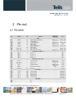
3 Pin-out
3.1 Pin table
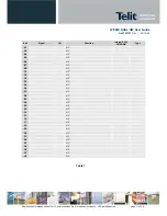
Ball
Signal
I/O
Function
Internal PULL
UP/DOWN
Type
SDIO
A1
SDIO[0]
I/O
SDIO DATA[0] (or SPI MISO)
10KOhm pull-up
SDIO (or SPI)
B2
SDIO[1]
I/O
SDIO DATA[1]
(or SPI INTERRUPT)
10KOhm pull-up
SDIO (or SPI)
A2
SDIO[2]
I/O
SDIO DATA[2]
10KOhm pull-up
SDIO
B3
SDIO[3]
I/O
SDIO DATA[3]
(or SPI CHIP SELECT)
10KOhm pull-up
SDIO (or SPI)
A3
SDIO_CLK
I/O
SDIO CLOCK
(or SPI CLOCK)
-
SDIO (or SPI)
A4
SDIO_CMD
I/O
SDIO CMD (or SPI MOSI )
10KOhm pull-up
SDIO (or SPI)
Testing and Certification
C3
TEST_1
O
Test line n. 1
-
TEST
C4
TEST_2
I
Test line n. 2
-
TEST
C5
TEST_3
I
Test line n. 3
-
TEST
D5
TEST_4
I
Test line n. 4
-
TEST
Miscellaneous Functions
B1
EN_A*
I
Enable/shut-down
10KOhm pull-up
control
C1
MR_RESET*
I
Manual reset
100KOhm pull-
up
control
D1
EN_B*
I
Enable/shut-down
10KOhm pull-up
control
D2
RESET
I
Reset for host processor
47KOhm pull-
down
control
H5
RF_ANT
RF
RF output
-
antenna
Power Supply
E1
VDD
PWR
Power input pin
-
power supply
E2
VDD
PWR
Power input pin
-
power supply
F1
VCC_A
PWR
Power input pin
-
power supply
F2
VCC_A
PWR
Power input pin
-
power supply
F3
VCC_A
PWR
Power input pin
-
power supply
RESERVED
1
A5
N.C.
A6
N.C.
1
All the reserved pins must be kept not connected (N.C.)


