JF2 Hardware User Guide
1vv0300985 Rev.4 2013-04-09
Reproduction forbidden without written authorization from Telit Communications S.p.A. - All Rights Reserved.
Page 20 of 40
Mod. 0805 2011-07 Rev.2
7.3.
SPI Mode
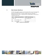
If both the GPIO6 and GPIO7 pins are left floating, the JF2 will power up in slave SPI mode,
supporting both SPI and Microwire formats. In this mode, the four pins are defined below:
Signal Name
SPI Function
GPIO7
SPI Chip Select (CS#)
GPIO6
SPI Clock (CLK)
RXA
SPI Data In (MOSI)
TXA
SPI Data Out (MISO)
Table 5 – SPI Mode Pin Assignments
NOTE:
Data rates of 6.8 MHz are achievable.


