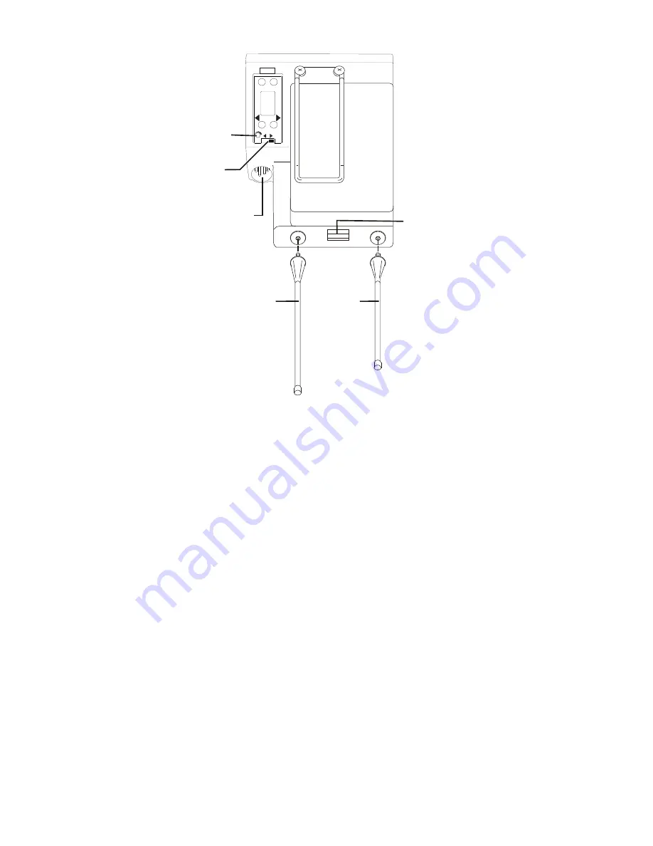
An tenna Con nec tion
The beltpack co mes with two de tach able, screw type, ¼ wave
an ten nas. To at tach the two an ten nas, screw into the re cep ta -
cles at the bot tom of the beltpack. The color dot on the screw
end of the an tenna must match the color dot on an tenna re cep -
ta cle. The lon gest an tenna is the re ceiver an tenna. It screws
into the left re cep ta cle if the beltpack is lay ing flat with the
bat tery com part ment face up and the an tenna re cep ta cles fac -
ing you. The other an tenna is the trans mit an tenna. New an -
tennas can be or
dered if de
sired, see the “Ac
ces
sories”
sec tion.
Trans mit mode
The rear panel lo cated trans mit switch has the fol low ing two
modes:
Push-to-Talk (PT TALK) – Rec om mended po si tion
–
The trans mit ter is al ways on. No au dio is sent un less the
talk switch is pressed.
Push-to-Transmit (PT TX) –
The trans mit ter and au dio
paths are off ex cept when the talk switch is pressed.
Head set Con nec tion
In sert the head set plug into the XLR con nec tor. See the head -
set pinout in the “TR-700 beltpack con trols and con nec tions”
sec tion if this is not a Telex head set. A dy namic or electret
head set mi cro phone is au to mat i cally de tected by the beltpack
and a bias volt age sup plied if needed.
4-9
M
E
N
U
S
E
T
MIC
PT
TX
PT
TALK
MICROPHONE
GAIN CONTROL
TRANSMIT
SWITCH
HEADSET
CONNECTION
RECEIVE
ANTENNA
TRANSMIT
ANTENNA
BATTERY
RELEASE
LATCH
Fig ure 19
TR-700 Rear Panel
Summary of Contents for RadioCom BTR-700
Page 1: ...Telex Operating Instructions RadioCom BTR 700 TR 700 Professional Wireless Intercom System ...
Page 2: ......
Page 4: ......
Page 12: ...2 4 Blank ...
Page 16: ...3 4 Blank ...
Page 26: ...4 10 Blank ...
Page 28: ...5 2 Blank ...
Page 48: ...7 2 Blank ...
Page 50: ...8 2 Blank ...
Page 52: ...9 2 Blank ...
Page 54: ...10 2 Blank ...
Page 56: ...11 2 Blank ...
Page 58: ...12 2 Blank ...
Page 60: ...13 2 Blank ...
Page 62: ...14 2 Blank ...
Page 64: ...15 2 Blank ...
Page 66: ...16 2 Blank ...
Page 67: ......


