background image


15

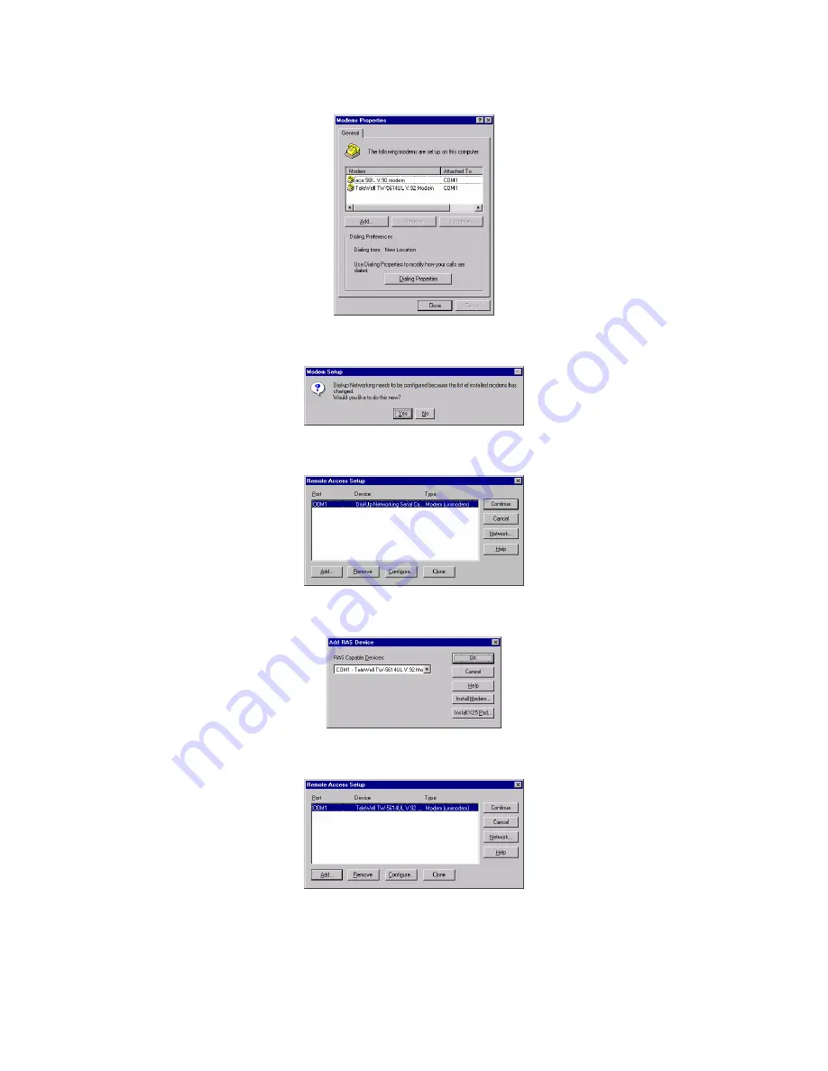
9.  You can see the modem set up on your PC. Click 

Close

 to go into next step. 


10. Click 

Yes

 to configure Dial-up Network. 


11. Click 

Add

 to add the device you installed. 


12.  Select the correct device you want to use and then click 

OK


13. Click

 Configure

 to select port usage. 


Summary of Contents for TW-5614UL

Page 1: ...TeleWell TW 5614UL V 92 V 90 Modem User s Manual...

Page 2: ...ephone Set 6 4 5 Verifying Your Connection 7 4 6 Connecting Microphone And Speaker 7 4 7 Configuring External Modem With Windows 95 98 ME 2000 NT4 0 8 4 8 Tips On Configuring Your Communication Softwa...

Page 3: ...application programs The voice capability renders a wide range of application possibilities from a simple telephone answering device to a sophisticated voice mail system The optional SVD feature allow...

Page 4: ...s or above AA Auto Answer Lights when the modem is in auto Answer mode Flashes when ring signal is received CD Carrier Detect Lights when carrier signal is received from remote modem OH Off Hook Light...

Page 5: ...ternal Modem Back Panel LINE Line RJ 11 jack PHONE Telephone RJ 11 jack SPK Speaker mini phone jack MIC Microphone mini phone jack SERIAL PORT Serial DB 9 female connector AC AC jack Power switch Powe...

Page 6: ...onnect your External Modem to the telephone line 1 Locate an available RJ 11 modular jack telephone outlet 2 Take one end of the modular cord supplied with the External Modem and plug it into the LINE...

Page 7: ...telephone number For example if your External Modem is connected to the telephone line 555 2121 and touch tone dialing is supported in your area type ATDT 5552121 Enter 3 You should hear the busy sig...

Page 8: ...refer to the installation below 1 Restart the computer after connecting the modem to PC When Windows detects the modem the message This wizard searches for new drives for TeleWell TW 5614UL V 92 Modem...

Page 9: ...files search for the device TeleWell TW 5614UL V 92 Modem and the location of driver Click Next 5 Windows has finished installing the software Click Finish to complete installation 6 And then Windows...

Page 10: ...is displayed Select Automatic search for a better driver or Specify the location of the driver then click Next 2 Select TeleWell TW 5614UL V 92 Modem whose location is E DRIVERS WINME E is your CD RO...

Page 11: ...ecting the modem to PC When Windows detects the modem the wizard will help you to install the new device Click Next to begin installation 2 Select Search for a suitable driver for my device Then click...

Page 12: ...F Drivers Win2k F is your CD ROM Then click OK 5 Wizard found the correct driver for the new device Then click Next 6 To continue the installation click Yes 7 Windows has finished installing the soft...

Page 13: ...13 Windows NT4 0 1 Double click Modems from Start Setting Control Panel 2 Click Add to add a new modem 3 Check Don t detect my modem I will select it from a list and then click Next 4 Click Have Disk...

Page 14: ...your CD ROM and then click OK 6 Select the model of your modem and then click Next 7 Select the COM port that you connect modem to your PC and then click Next 8 Windows has finished installing the so...

Page 15: ...on your PC Click Close to go into next step 10 Click Yes to configure Dial up Network 11 Click Add to add the device you installed 12 Select the correct device you want to use and then click OK 13 Cli...

Page 16: ...lect the port usage and then click OK 15 Click Network to select network configuration 16 Select network configuration and then click OK 17 Click Continue to go into next step 18 Click Yes to restart...

Page 17: ...cting with a remote External Modem 3 Many communication software uses the modem response to control program flow Make sure that the software is set to recognize a CONNECT 28800 response If this does n...

Page 18: ...described in succeeding sections pp any parameters that is required by the command If you make a mistake while typing a command press the Backspace key to delete the error To make a command line easy...

Page 19: ...is identified as n in the left column and described in the right column IMPORTANT Each command except for and A must be preceded by AT and executed when you press the Enter key To review the format us...

Page 20: ...by OK 2 To read values from more than one S Register type ATSr Sr Enter where r specify the different S Register numbers For example to read the value of Register S0 number of rings before answering...

Page 21: ...me a signal is detected an qualified as a carrier This timing lets your modem ignore spurious signals that are the same frequency as the carrier Higher S9 values reduce the chance of a carrier being d...

Page 22: ...extended responses are also available that shows the carrier speed compression method and the error correction protocol as described in the following table You can enable the extended responses by us...

Page 23: ...x CARRIER 14400 52 x x x x x CARRIER 16800 53 x x x x x CARRIER 19200 54 x x x x x CARRIER 21600 55 x x x x x CARRIER 24000 56 x x x x x CARRIER 26400 57 x x x x x CARRIER 28800 58 x x x x x CONNECT 1...

Page 24: ...xternal Modem responses X0 The X0 response set consists of the first five responses as well as the NO ANSWER response X1 The X1 response set consists of the first five responses as well as NO ANSWER a...

Page 25: ...mber Diagnostics Power on self test V 54 loop test VOICE OPERATION Operation Analog Simultaneous Voice and Data ASVD Telephone Answering Machine TAM Voice mail system Sampling Rate Voice 7 2 KHz using...

Page 26: ...by one or more of the following measures 1 Reorient of relocate the receiving antenna 2 Increase the separation between the equipment and receiver 3 Connect the equipment into an outlet on a circuit d...

Page 27: ...connect to your line as determined by the REN you should contact your local telephone company to determine the maximum REN for your calling area If your equipment causes harm to the telephone network...

Page 28: ...28 Appendix A 3 CE Mark Declaration This is a Class B product In a domestic environment this product may cause radio interference in which case the user may be required to take adequate measures...

Page 29: ...ne command mode without disconnection D2 Normal DTR operations F Load Factory Configuration Profile Hn Disconnect Hang up H0 Hang up go on hook H1 Go off hook In Identification I0 Report product code...

Reviews: