background image

EN

9

5. WEB NMS operation 

User  not  only  can  use  front  buttons  for  setting  configuration,  but  also  can 

control  and  set  the  configuration  in  computer  by  connect  to  web 

NMS


Port

. User should ensure that the computer’s IP address is different from the 

NDS3542’s IP address; otherwise, it would cause IP conflict. 

5.1 Login 

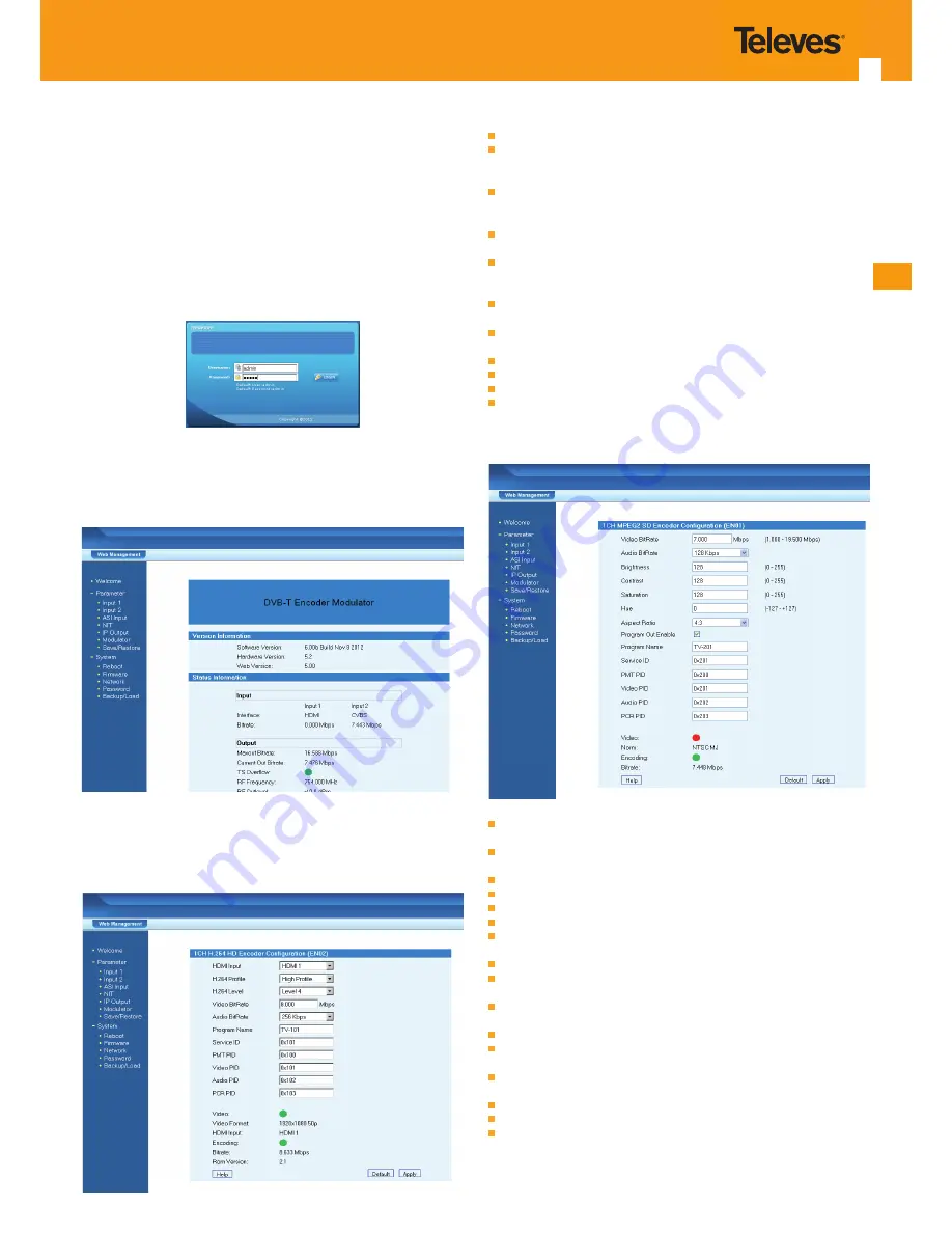
A  login  interface  will  pop  up  firstly  when  user  entered  the  IP  address: 

http://192.168.0.136 (

or shown in 5.1 IP Address menu

), the interface shows as 

follow picture. Both of the default user name and password are 

admin

.

User will face welcome interface after login, and all setting options are been 

listed  on  the  left  side.  And  the  main  window  at  the  right  shows  version 

information  and  status  information.  (All  the  example  pictures  been  showed 

here  just  window  captures  pictures  when  the  device  connected  in  our  test 

room, status shows on the picture just for reference, they are not fixed value).

5.2 Configuration setting 

1) HDMI input setting

  HDMI Input: Display which HDMI port is used (Only for HDMI Band Input).

  H.264 Profile: user can set the H.264 Profile in this area, there are four possible 

options  provided  to  be  selected:  Automatic,  High  Profile,  Main  Profile  and 

Baseline Profile.

  H.264 Level: user can set the H.264 Level in this area, there are twelve possible 

options provided to be selected: Automatic, Level 1.2, Level 1.3, Level 2, Level 

2.1, Level 2.2, Level 3, Level 3.1, Level 3.2, Level 4, Level 4.1 & Level 4.2.

  Video  bit  rate:  user  can  set  the  video  bit  rate  in  this  area,  the  range  is 

1~19.5Mbps. 

  Audio bit rate: user can set the audio bit rate in this area, there are five possible 

options provided to be selected: 64kbps, 96kbps, 128kbps, 192kbps, 256kbps 

and 320kbps. The default value is 128kbps. 

  Program  name:  it  shows  current  program  information.  User  can  select  and 

type the program name to be played as needed. 

  PMT/Video/Audio/PCR PID: in this area, user can set program PIDs as needed, 

usually system will automatically select the default values. 

  Encoding and video light: the light should show green colour normally 

  HDMI input: it shows if there is real-time HDMI signal inputting 

  Video format: the current video format of the device 

  Bit rate: the current encoding bit rate

2) 1 A/V input setting

  Video Bit Rate: The range of values from 1.000 to 19.500 Mbps. For SD signal, 

3.000 Mbps is ok, HD signal at least need 6.000 Mbps.

  Audio  Bit  Rate:  Audio  encode  bit  rate  configuration.  You  can  select  the 

suitable audio bit rate from list.

  Brightness: The range of values from 0 to 255 (Only for SD signal).

  Contrast: The range of values from 0 to 255 (Only for SD signal).

  Saturation: The range of values from 0 to 255 (Only for SD signal).

  Hue: The range of values from -127 to 127 (Only for SD signal).

  Aspect Ratio: User can set the Aspect ratio. There are 4 possible options to be 

selected: 1:1, 4:3, 16:9 and 2.21:1.

  Program Out Enable: Enables / Disables the program out.

  Program Name: Only support character and number. The length can not over 

32 byte

  Service  ID:  Also  called  program  number,  it  is  must  different  from  other 

program. If you change it,you should modify the LCN.

  PMT PID: Program Mapping Table PID

  Video: Green is normal, red means signal input error, please check signal input 

and video format.

  Encoding:  Green  is  normal,  red  means  encoder  is  not  work,  please  check 

signal input and video format.

  Norm: Display the video format of the input (Only for SD signal).

  Video Format: Display the video format of the input (Only for HD signal).

  Bit rate: Display the current encoder Bit rate.

Summary of Contents for 554501

Page 1: ...DVB T Modulators EN Refs 554501 554601 User s Manual w w w t e l e v e s c o m ...

Page 2: ......

Page 3: ...ion precautions 6 3 Operation 6 3 1 Button introduction 6 3 2 Initial status 6 3 3 General setting for main menu 6 4 Encoders 8 4 1 Specification 8 5 Web nms operation 9 5 1 Login 9 5 2 Configuration setting 9 6 Troubleshooting 12 7 Application 12 7 1 Ordering guideline 12 7 2 Application example 13 7 3 Configuration example for more than one unit in the same installation 13 ...

Page 4: ...s in addition to being the best choice for public premises which offer sporting events VIP entertainment channels and other 1 2 Blocks diagram 1 3 Technical specifications DVB T modulator section Standard EN300744 FFT mode 2K 8K Bandwidth 6M 7M 8M Constellation QPSK 16QAM 64QAM Guard Interval 1 4 1 8 1 16 1 32 FEC 1 2 2 3 3 4 5 6 7 8 MER 42dB RF frequency 30 960MHz 1KHz step RF output level 30 10d...

Page 5: ...6 12 13 15 14 4 5 6 7 8 9 1 554501 554601 1 LCD display 2 NMS port 3 IP port 4 ON LED and alarm LED 5 Locking LED 6 Up Down and Left Right buttons 7 ENTER button 8 MENU button 9 Locking button 10 Encoder 1 slot open 11 Encoder 2 slot with tap 12 RF input 13 RF output 14 ON OFF switch 15 Mains socket ...

Page 6: ... when power On Setting value up and moving up To move left To move right Setting value down and moving down Back step Confirm setting Lock button 3 2 Initial Status Switch On then below status will be displayed few seconds initialization then open startup picture DVB T indicate the modulation standard of this device XXX XX MHz indicate the output frequency and the frequency range is 30 960MHz X XX...

Page 7: ...evel and press ENTER to confirm 4 IP Output Setting 4 5 Gateway 4 6 Port 4 1 IP Output 4 2 Service IP 4 3 Output IP 4 4 Subnet Mask 4 5 Gateway 4 6 Port 4 1 IP Output 4 2 Service IP 4 3 Output IP 4 4 Subnet Mask User can press UP DOWN to choose this item Enter and LEFT RIGHT to set the parameters If not set the following parameters will be no use the IP Output will not work IP Output The IP Output...

Page 8: ...ion MPEG 2 SD MPEG 2 SD MPEG 2 SD Encoding mode MPEG 2 H264 AVC SD HD Input port Option 1 Port 1 One channel CVBS input Unbalanced audio input Port 2 One channel CVBS input Unbalanced audio input RF input Option 2 Port 1 Two channel CVBS input Unbalanced audio input Port 2 Two channel CVBS input Unbalanced audio input RF input Option 3 Port 1 One channel of HDMI input Port 2 One channel of HDMI in...

Page 9: ...ps 96kbps 128kbps 192kbps 256kbps and 320kbps The default value is 128kbps Program name it shows current program information User can select and type the program name to be played as needed PMT Video Audio PCR PID in this area user can set program PIDs as needed usually system will automatically select the default values Encoding and video light the light should show green colour normally HDMI inp...

Page 10: ...document Network name The name of current network user can change it as he likes Network ID This is a 16 bit field which identifies the terrestrial network that supports the service indicated User can click Add to pop up a table following is the interface Transport stream ID This 16 bit field which serves as a label identifying the TS which contains the service event or mosaic described by the cel...

Page 11: ...ticular program is necessary to put before the IP address for example udp 224 2 2 2 1234 Important Not all computers have the ability to view a service provided by a 554803 6 Modulator setting Bandwidth there are three possible options provided to be selected 6M 7M and 8M Constellation there also have three possible options to be selected QPSK 16QAM and 64QAM FFT user can set the FFT transmission ...

Page 12: ...nk on the rear panel and other heat sink bores if necessary Checking the input AC within the power supply working range and the connection is correct before switching on device Checking the RF output level varies within tolerant range if it is necessary Checking all signal cables have been properly connected Frequently switching on off device is prohibited the interval between every switching on o...

Page 13: ...rk Wireless router Eventual roof antenna IP optional Antenna Wall socket Camera TV TV TV TV Advertisement System Blue DVD Hard Disk Sender Pay Channel STB IRD STB 7 2 Application example 7 3 Configuration example for more than one unit in the same installation Unit 1 Unit 2 ...

Page 14: ...the menu of the next images 7 3 2 NIT Hierarchy and LCN Configuration In this menu is possible to edit the LCN of each program in order to be listed correctly the Hierarchy Information must be set to a 1 a 2 or a 4 the same on each unit of the same network The LCN can be set by any order in the image above it can be observed that the unit 2 will have program 1 3 and 4 and unit 1 will have program ...

Page 15: ...e ways to list the programs With LCN the programs are listed in order according with the LCN configuration set above Without LCN the programs list will depend on theTV STB and it can be based on Alphabetic order MUX frequency First the HD programs listed based on the MUX frequency Then the SD programs listed based on the MUX frequency ...

Page 16: ...DVB T Modulator 16 ...

Page 17: ...EN 17 ...

Page 18: ...DVB T Modulator 18 ...

Page 19: ...EN 19 ...

Page 20: ...564501_564601_003_EN televes com ...

Reviews: