background image


Page 18 of 21 


Security Key


Telescript's 

security key

 "unlocks" the software, and allows the 

prompting and Remote Update features to work. This is so that 
the software can be installed on as many computers as you like, 
but only the one with the security key attached will be allowed to 
scroll and receive updates. This is Telescript's only form of copy 
protection. 
 

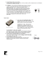
There are two types of security keys available: a classic 

parallel port

 dongle, 

and a more modern 

USB token

. Both provide the same functionality, but the 

setup is slightly different. 


Parallel port dongle installation


Locate the parallel port on your computer. 
The parallel port is a female connector, approximately 2½'' long, with 25 pins in two rows. 


1.  Un-attach the cable connected to the parallel port.


If there's already a cable attached to the parallel port, un-attach it. 


2.  Attach the dongle to the parallel port.


Plug the male side of the dongle into the parallel port, and tighten the mounting screws as you like. 


3. 

Re-attach the cable to the security key.


If you had to un-attach a cables previously, simply re-attach it onto the "pass-through" (female) side of the 
security key.  

USB token installation


1.  Install the TeleScript software.


Before you attach the USB token, make sure that you have the 

TeleScript 

software installed. 


2.  Locate an available USB port on your computer.


A USB port is approximately ½'' in diameter, rectangular in shape. Note that a 

USB hub

 may be used to add 

additional USB ports to a computer. 


3.  Plug the token into the USB port.


Simply put, just plug in the token and watch the computer configure it for you.  


Summary of Contents for Fold and Go DV8

Page 1: ...Page 1 of 21 Setup Instructions ...

Page 2: ...ntents 1 Parts and accessory list page 3 2 Mounting Configuration 1 DV Camera Configuration page 4 3 Mounting Configuration 2 ENG Configuration page 8 4 Display Adjustment page 12 5 Spec sheet page 14 6 Computer Setup page 15 ...

Page 3: ...or and folding Lensview assembly 4 Folding hood and conical mask 5 Removable side panels 6 Mounting hardware screws and washers 7 Power and video input cable harness 8 Power supply Optional equipment Custom case Counter Balance Weight or Battery adapter plate 1 2 1 3 1 4 1 5 1 7 1 8 1 6 1 ...

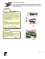
Page 4: ... over the threaded holes on the bottom of the GlidePlate Using the screws provided with the wedge plate and a flat head screwdriver attach the wedge plate to the GlidePlate Secure the configured GlidePlate to the tripod and LOCK the video head Option 2 If the tripod has just an attachment screw position the appropriate threaded hole in the bottom of the GlidePlate over the attachment screw and sec...

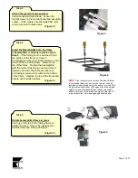
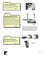
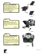
Page 5: ... the channel under any protruding screws until it rests on the bottom of the frame Replace the top of the frame and secure with 2 slotted screws Figure 4 Step 5 Rotate beamsplitter frame in place Push up on the top of the folding frame to rotate into place Secure by inserting two thumbscrews and turning until tight Figure 5 Figure 3 HINT If the reflective correct side of the BeamSplitter is not ma...

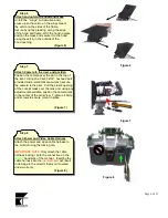
Page 6: ... hexhead bolt provided and a small crescent wrench secure the camera to the riser Pull the elastic opening of the concial mask over the lens and using any adjustments available position the camera lens in the center of the LensView Tighten all bolts and screws to secure mount in place Figure 7 Step 8 Attach Power and Video Cable Harness Attach the power and video cable harness to the monitor using...

Page 7: ...ting computer a VGA to composite video scan converter may be required to generate a composite video signal Figure 9 Step 10 Turn the display on Locate the Power button on the monitor and press it once to turn the monitor on Panel text identifiers should briefly display on the screen Figure 10 Figure 9 Figure 10 Power button ...

Page 8: ...the threaded holes on the bottom of the GlidePlate Using a flat head screwdriver and the screws provided with the wedge plate attach the wedge plate to the GlidePlate Secure the configured GlidePlate to the tripod and LOCK the video head bottom side with the beveled slot Figure 1 Step 2 Attach the Camera Quick Release Plate Position the camera quick release plate over the top non beveled side of t...

Page 9: ... the channel under any protruding screws until it rests on the bottom of the frame Replace the top of the frame and secure with 2 slotted screws Figure 4 Step 5 Rotate beamsplitter frame in place Push up on the top of the folding frame to rotate into place Secure by inserting two thumbscrews and turning until tight Figure 5 Figure 3 HINT If the reflective correct side of the BeamSplitter is not ma...

Page 10: ...a Insert the camera into the Camera Quick Release Plate that was attached to the GlidePlate in Step 2 Pull the conical mask around the lens and adjust the hood height if necessary Figure 7 Step 8 Attach Power and Video Cable Harness Attach the power and video cable harness to the monitor using the locking clip IMPORTANT NOTE Only attach the cable harness locking clip to the connection on the RIGHT...

Page 11: ...ting computer a VGA to composite video scan converter may be required to generate a composite video signal Figure 9 Step 10 Turn the display on Locate the Power button on the monitor and press it once to turn the monitor on Panel text identifiers should briefly display on the screen Figure 10 Figure 9 Figure 10 Power button ...

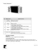
Page 12: ...n sub menu options 3 Adjustment of menu value Selected value increase 6 Menu Displays On Screen Menu 7 Video S Video Changes video input options Note S Video input requires optional cable PICTURE ADJUSTMENT Brightness Press 4 up or 5 down to adjust the monitor brightness COLOR CONTRAST TINT Press the 6 Menu key on the monitor to activate the on screen menu Press the 4 up or 5 down keys to choose C...

Page 13: ...eys to select POWER SAVING ON or POWER SAVING OFF Once selected press the 6 Menu key to confirm setting FSC SET 3 58 MHZ Press the 6 Menu key on the monitor to activate the on screen menu Press the 4 up or 5 down keys to choose FSC SET 3 58MHz Press 6 menu to enter selection mode Use the 4 up or 5 down keys to select 3 58MHz FSC SET 4 43 MHz Once selected press the 6 Menu key to confirm setting HO...

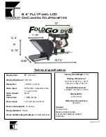
Page 14: ...DC via 4 pin XLR Power Consumption 10 W max Display Material Plastic Frame and Mounting Hardware Aircraft aluminum 19 75 12 5 to 10 75 7 75 12 Total System Weight 5 lbs Display Dimensions 8 23 W x 6 24 D x 1 24 H 209 W x 31 5D x 158 5 H Mounted Dimensions 10 65W x 19 75 D x 10 75H Beamsplitter 8 W x 6 5 D Reflective Transmissive 30 70 Options Custom Case Battery adapter plate 5 lb counter balance ...

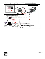
Page 15: ...Morning Welcome to the 3 rd Annual meeting of Computer Mouse Telescript 10 button hand controller 110 220v 15 20A power source Coaxial Cable AC Power Cable VGA Cable Serial Cable Telescript Parallel or USB Security Key Table AC Adaptor VGA to NTSC Scan Converter not needed if SVideo or direct VGA connection is used Composite Video Power Power Power Serial Telescript DV8 Composite Video Input Power...

Page 16: ... on it One which is typically blue is a male connector it has pins that stick out This connector which may also have PC printed on it should be connected to the VGA port on the back of your computer Most VGA connectors on the computer are also blue or have a monitor icon next to the port If you re using a computer with an external monitor that connects to the VGA port such as a typical desktop com...

Page 17: ...ntrol 1 Telescript s custom serial hand control provides direct control over the prompter including start stop speed inverse video previous and next script and other commonly used commands A standard RJ 11 cable also known as a telephone cable is used to connect the controller to your computer an RJ 11 to Serial adapter then attaches to your computer s serial port to complete the connection Both c...

Page 18: ...ins in two rows 1 Un attach the cable connected to the parallel port If there s already a cable attached to the parallel port un attach it 2 Attach the dongle to the parallel port Plug the male side of the dongle into the parallel port and tighten the mounting screws as you like 3 Re attach the cable to the security key If you had to un attach a cables previously simply re attach it onto the pass ...

Page 19: ... 2 Audio out connector not used for prompting 3 USB Port 4 Parallel port 25 pins 5 Serial port 9 pins some new laptops may not have a serial port and may require a Serial to USB adapter 6 VGA port 15 pins 7 PS 2 Mouse Keyboard port 8 Power connector Security Keys 10 Button Serial Hand Controller Scan Converter model may vary Mouse AC Adaptor ...

Page 20: ...tallShield interface which provides a wizard style step by step procedure with on screen instructions plus it allows you to choose among installation options To start the installation insert the Telescript software CD ROM into your computer s CD drive the InstallShield Wizard should then appear within a few seconds Then just follow the on screen instructions 1 Start the wizard by inserting the CD ...

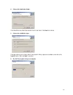
Page 21: ...isted will be fine for most users Click Next to continue 3 Choose the installation type This page allows you to choose what components of the program are installed Just click on the Typical button then click Next to continue 4 See the files copied onto your computer ...

Reviews: