


-53-
§
§
3
3
.
.
2
2
.
.
8
8
.
.
2
2
.
.
2
2
O
O
u
u
t
t
p
p
u
u
t
t
C
C
h
h
a
a
n
n
n
n
e
e
l
l
B
B
i
i
t
t
R
R
a
a
t
t
e
e
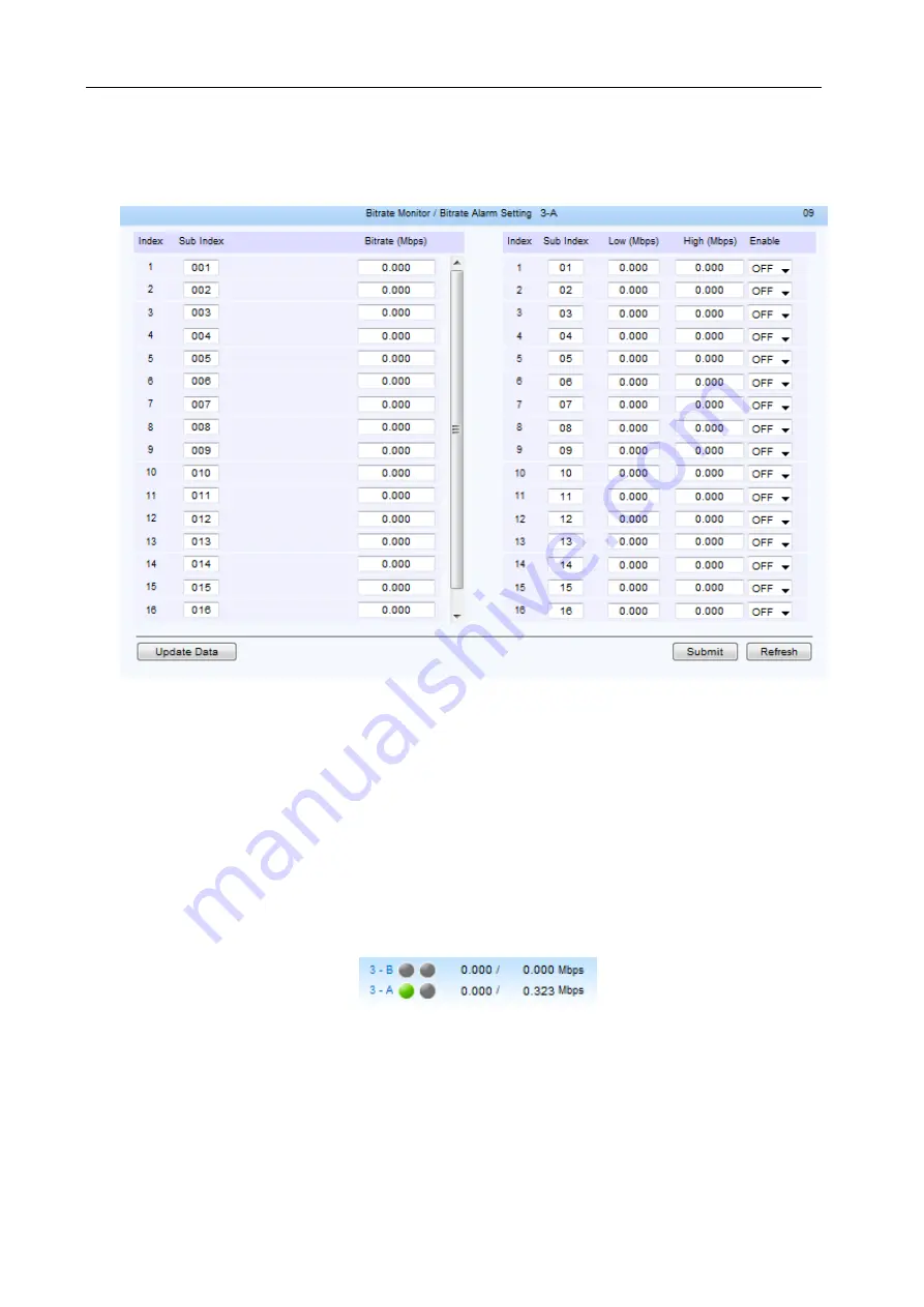
Unfold the “Output Channel” menu to enter the output channel bit rate monitoring page, shown as below:
Fig.62
Output Channel Bit Rate Monitoring
Shown as figure 62, the left column displays the real-time bit rate of each channel; the right column
enable users to set the bit rate alarm setting, including lower limit, upper limit, and the enable switch
Lower Limit:
when the real-time bit rate is lower than this lower limit value, it will trigger an alarm.
Upper Limit:
when the real-time bit rate is higher than this upper limit value, it will trigger an alarm.
Enable Switch:
turn ON/OFF the alarm.
When finish the settings, click “Submit” button to validate them.
§
§
3
3
.
.
2
2
.
.
8
8
.
.
2
2
.
.
3
3
S
S
y
y
s
s
t
t
e
e
m
m
B
B
i
i
t
t
R
R
a
a
t
t
e
e
The bottom of the page displays the system input, output, and insert bit rate of each daughter board,
shown as below:
Fig.63
System Bit Rate Monitoring
The left value is the total input rate; the right value is the total output rate.


