


Installation of the Berkeley Jet Control closely follows that of the other
MV-3 Controls made by Telefl ex Marine Controls. Follow the instructions
in this booklet plus these few added instructions:
Neutral Safety Switch Option
A neutral safety switch kit is available for use with
Berkeley jet versions (Part Number 311453).
Follow the procedures for installation of the
Neutral Safety Switch as outlined page 5.
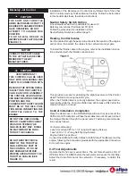
Routing Control Cables
Run the cables through the panel cutout back to the location of the engine
and jet drive, then attach the cables to the carburetor and jet gate.
To install the throttle cable to the engine, refer to the installation instruc-
tions provided with the throttle connection kit.
This provides a means for absorbing the slight movement of the Control
Head Throttle Arm during the shift cycle.
When the Throttle Cable is correctly adjusted, the engine speed will re-
main at idle while the Control is shifted and will increase ONLY after the
Gate is full open or closed.
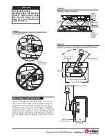
Control Installation Completion
Place the Hand Lever in the FORWARD position so that, as a result, the
Shift Arm and Throttle Arm will take the smallest amount of space to feed
the Hanger Bracket through the panel cutout. Fastening recommenda-
tions are as follows:
For Normal Mounting:
2 each, Oval Head #10 x 1-1/4” long Self-Tapping Screws.
1 each, #10 x 1-1/2” long Self Tapping Screws.
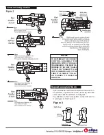
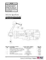
Engine Cable Connections:
THE SHIFT AND THROTTLE
ARMS HAVE BEEN OFFSET 15
DEGREES TO ASSURE PROPER
GATE OPERATION. DO NOT
ATTEMPT TO CHANGE THIS
POSITION.
TO DO SO WILL RESULT IN
IMPROPER SHIFT ACTION (SEE
FIGURE 11).
CAUTION
!
Berkeley Jet Control
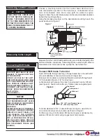
NOTICE
CONNECT THE SHIFT CABLE
TO THE JET GATE AS RECOM-
MENDED BY THE JET
MANUFACTURER..
VERY IMPORTANT!
THIS CONTROL CAN BE USED
ONLY WITH NON-SPRING LINK
THROTTLE CONNECTION KITS.
BECAUSE THE SPRING DWELL
IS BUILT INTO THE THROTTLE
CABLE ANCHOR ASSEMBLY,
THE CONTROL HEAD HAND LE-
VER MUST BE IN THE FORWARD
POSITION AND THE
CARBURETOR THROTTLE ARM
MUST BE AT THE IDLE POSI-
TION WHILE CONNECTING THE
THROTTLE CABLE TO THE
ENGINE.
CAUTION
!
Connect the Shift and Throttle Cables to the Shift and Throttle levers at the
engine, following the instructions provided with the appropriate Connec tion
Kit or with the engine.
9.4 Final Adjustments
Operate the Hand Lever several times. The Jet Gate should be FULLY
OPEN or FULLY CLOSED before the carburetor arm leaves the Idle Stop.
Adjust the Cable Terminal at the carburetor, if necessary, to obtain this
result.
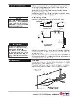
DO NOT USE CABLE HANG-
ERS OR CLAMPS WHICH MAY
CRUSH OR STRESS THE
CABLES IN ANY WAY. DOING
SO MAY IMPAIR THE FUNC-
TION OF THE CABLES.
DO NOT RESTRICT MOVE-
MENT OF THE THROTTLE
CABLE WITHIN 2 FEET OF
THE CONTROL. TO DO SO
MAY DAMAGE OR IMPAIR
PROPER OPERATION OF THE
THROTTLE CABLES (SEE
FIGURE 10).