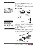
Choose a mounting location for the control head which will pro-
vide comfortable operation of the hand lever, unobstructed move-
ment of mechanism arms and a clear path for cables to engine.
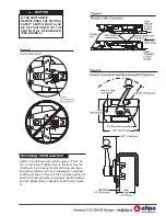
Figure 6 shows the control dimensions and the recommended clearance
behind the mounting surface.
Using the template provided, cut the appropriate mounting hole in the
panel as shown in Figure 7.
Measure from the control head position along an unobstructed path to the
shift and throttle connections. Cable lengths are overall length. When a
measurement is in feet and inches, specify the next whole foot.
Connect Shift Cable To Control
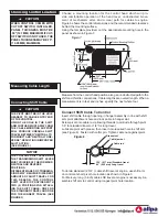
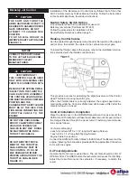
Insert shift cable through opening in hanger assembly in line with shift
arm pivot attachment hole and lock cable in hanger slot.
Screw pivot onto cable rod, allowing threads to protrude through pivot
1/8” for standard travel or 1/4” for long travel.
Lubricate pivot with grease, then insert into required hole in shift arm
(see Figure 8). Fasten with cotter pin. Tighten cable nut against pivot.
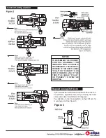
To obtain standard (2 3/4” ) cable shift travel at engine, use shift arm
on control at short pivot hole location as shown in Figure 3.
For Mercury, long (3 inch) cable shift travel at engine is necessary. As-
semble shift arm to control using longest pivot hole location.
CAUTION
!
WHEN CONTROL COMES WITH
CUTOFF SWITCH INSTALLED,
PANEL THICKNESS MUST BE
.50” (12.7 MM) MAXIMUM. IF CUT-
OFF SWITCH IS NOT USED, THE
PANEL THICKNESS MAY BE .75”.
(19.05 MM) MAXIMUM.
Choosing Control Location
Measuring Cable Length
Connecting Shift Cable
CAUTION
!
THE PIVOT MUST BE IN THE HOLE
NEAREST TO CABLE ENTRY END
OF THE CONTROL.
USING THE HOLE IN THE SHIFT
ARM FURTHER MOST AWAY FROM
THE CABLE MOUNTING SUPPORT
WILL PRODUCE UNEQUAL SHIFT
TRAVEL BETWEEN “NEUTRAL TO
FORWARD” AND “NEUTRAL TO RE-
VERSE”, RESULTING IN IMPROPER
SHIFT ACTION.
(SEE FIGURE 3.)
NOTICE
THE CONTROL SHIFT LEVER AND
THE TRANSMISSION SHIFT LEVER
MUST COINCIDE AT THE FORWARD,
NEUTRAL AND REVERSE
POSITIONS.
DIFFERENT MAKES OF TRANSMIS-
SIONS MAY REQUIRE DIFFERENT
AMOUNTS OF SHIFT TRAVEL. FOR
THIS REASON, THE CONTROL
SHIFT LEVER IS PROVIDED WITH
TWO (2) POSITIONS FOR ATTACH-
ING THE SHIFT CABLE: ONE FOR
THE STANDARD TRAVEL AND ONE
FOR THE LONGEST TRAVEL. (SEE
FIGURE 3)
Figure 8
Brass pivot
Cable jam nut
Cable rod
.125" (3.17 mm) Standard travel
.25" (6.35 mm) Long travel

