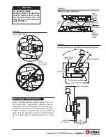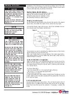
With opening in swivel bracket nearest to the cable entry end of the
control, insert throttle cable through opening in swivel bracket and
secure cable hub in bracket slot.
Screw pivot onto cable rod and allow cable rod threads to protrude
through pivot 1/8 inch (3.17mm).
Lubricate pivot with grease, then insert into hole in throttle arm. Fasten
with cotter pin. Tighten cable nut against pivot.
Section 4
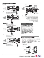
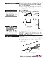
Neutral Safety Switch
Most MV-3 controls are equipped with a neutral safety switch.
With the Control in NEUTRAL, connect one wire of the tester to the com-
mon terminal and one wire to the “NC” (Normally Closed) Terminal. The
test light MUST light.
Connect the Neutral Safety Switch between the ignition switch (start lead)
and the starter solenoid. (See Figure 9.) Use terminals with insulators to
insure against an electrical short circuit.
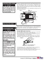
Cable Path
Run the cables, which are connected to the control, back to the throttle
and shift location of the engine and drive.
The cables should run as straight as possible, avoiding any sharp bends.
Make no bends in the cable of less than 8 inch (203.2 mm) radius.
NOTICE
TELEFLEX MARINE CONTROLS
STRONGLY
RECOMMENDS
THAT THE SWITCH BE CON-
NECTED TO ASSURE SAFE
BOATING OPERATION.
NC
CAUTION
!
CHECK TO MAKE SURE THAT
THERE IS ELECTRICAL CONTI-
NUITY ONLY WHEN THE
CONTROL IS IN NEUTRAL.
WHEN THE CONTROL IS IN
GEAR, THERE MUST NOT BE
ANY ELECTRICAL CONTINU-
ITY.
Figure 10
24.0" (609 mm)
Minimum
Loose tie
Allow 4.0" (101 mm)
for cable movement
Swivel
Bracket
Connect Throttle Cable
Mount Control

