Teledyne LeCroy
PCI Express Mid-Bus Probe for Summit Analyzers
Version 1.1
8
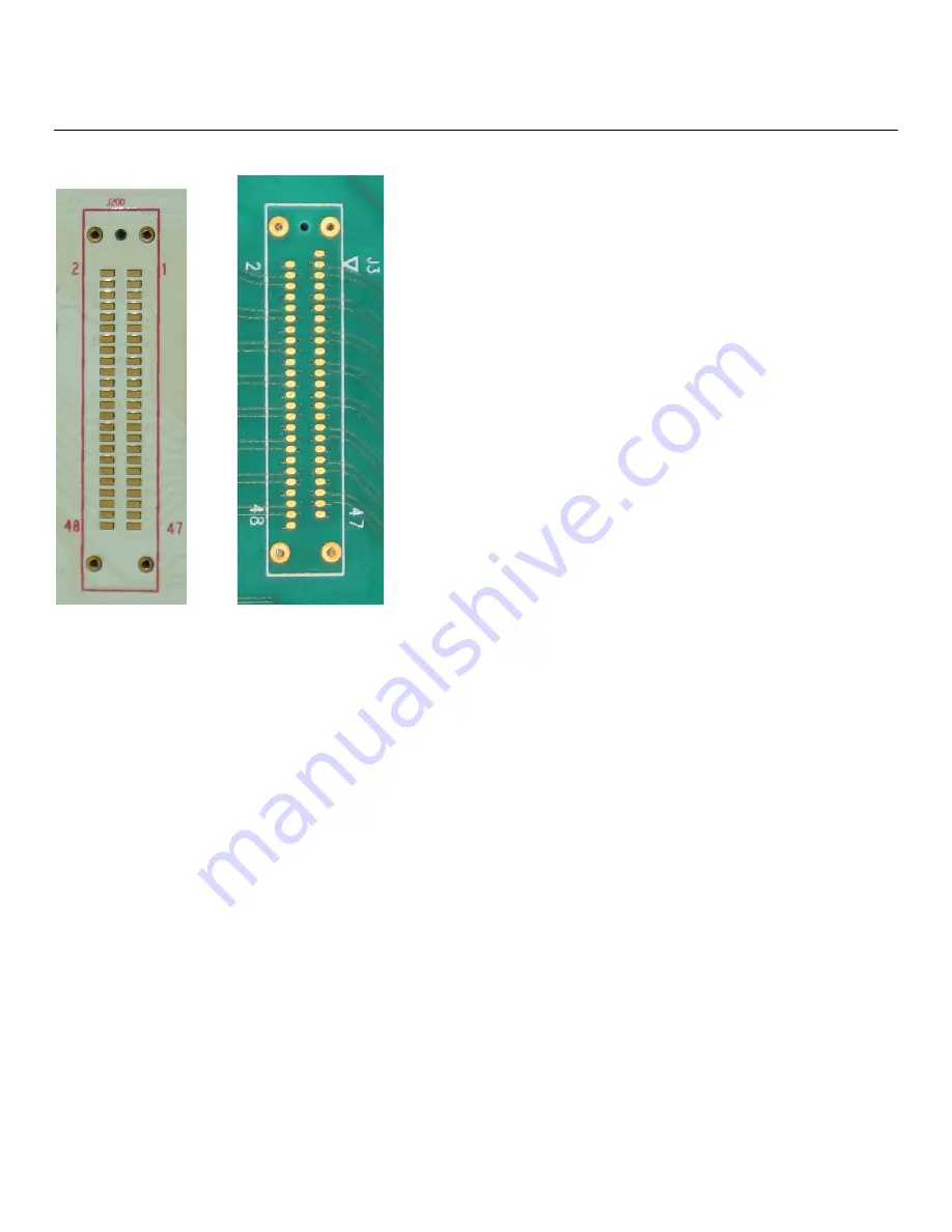
A typical layout of a mid-bus footprint might look something like the following two pictures:
Gen1 Mid-Bus Layout Gen2 Mid-Bus Layout
PCB Layout
Page 1: ...Protocol Solutions Group PCI Express 2 0 Mid Bus Probe for Summit Analyzers Installation and Usage Manual Manual Version 1 1 Generated on 2 7 2018 6 25 PM...
Page 2: ...ment without notice or penalty Trademarks and Servicemarks Teledyne LeCroy PETracer PCI Protocol Suite and Summit T2 16 Summit T3 16 Summit T3 8 Summit T28 and Summit T24 are trademarks of Teledyne Le...
Page 3: ...ane Widths 14 4 4 Pin Assignments for x8 Lane Widths 16 4 5 Pin Assignments for x4 Lane Widths 17 4 6 Pin Assignments for x2 Lane Widths 18 4 7 Pin Assignments for x1 Lane Widths 19 5 INSTALLATION OF...
Page 4: ...des direct probing capability of a PCI Express bus at a width of up to 16 lanes To accommodate a mid bus probe a special pad layout is required to expose the PCI Express differential pairs on the surf...
Page 5: ...ing and ground reference Should a reference clock RefClk be required a separate connection must be made Teledyne LeCroy PCI Express protocol analyzers can use a reference clock probe in conjunction wi...
Page 6: ...his section describes footprint dimensions keepout volumes and probe pin assignments 3 1 Probe Footprints The Summit T24 Mid bus Probe is fully compatible with the standardized mid bus footprint recom...
Page 7: ...Teledyne LeCroy PCI Express Mid Bus Probe for Summit Analyzers Version 1 1 7 Note All dimensions are in inches...
Page 8: ...eCroy PCI Express Mid Bus Probe for Summit Analyzers Version 1 1 8 A typical layout of a mid bus footprint might look something like the following two pictures Gen1 Mid Bus Layout Gen2 Mid Bus Layout...
Page 9: ...Teledyne LeCroy PCI Express Mid Bus Probe for Summit Analyzers Version 1 1 9 Note All dimensions are in inches...
Page 10: ...Croy PCI Express Mid Bus Probe for Summit Analyzers Version 1 1 10 A typical layout of a mid bus footprint might look something like the following two pictures Gen1 Mid Bus Layout Gen2 Mid Bus Layout...
Page 11: ...CB connector because it is not part of the electrical circuits of either the target system or the probe With the use of a retention module the requirement to have a keep out area on the backside of th...
Page 12: ...isting clock the header shall be located on the existing clock transmission line where a high impedance clock probe from the mid bus probe is connected with no significant loading effects In the case...
Page 13: ...With this unique design the Teledyne LeCroy mid bus probes can capture bus traffic signals with amplitudes specified by the PCI Express standard while introducing only the loss and added jitter that a...
Page 14: ...ind that any of modifications mentioned in Section 4 2 can be applied and in addition the lane swizzling feature of the Summit T3 16 and T2 16 systems noted in Section 4 2 x16 in Two Unidirectional Fo...
Page 15: ...Teledyne LeCroy PCI Express Mid Bus Probe for Summit Analyzers Version 1 1 15 x16 in Two Bi directional Footprints Mid Bus Probe Pinout on two Full size Headers Summit only...
Page 16: ...ame Pin Signal Name G1 GND Gen2 only 2 GND 1 C0p Upstream 4 C0p Downstream 3 C0n Upstream 6 C0n Downstream 5 GND 8 GND 7 C1p Upstream 10 C1p Downstream 9 C1n Upstream 12 C1n Downstream 11 GND 14 GND 1...
Page 17: ...entioned in Section 4 2 can be applied x4 Bi directional Mid Bus Probe Pinout on a Half size Header Pin Signal Name Pin Signal Name G1 GND Gen2 only 2 GND 1 C0p Upstream 4 C0p Downstream 3 C0n Upstrea...
Page 18: ...ended pin assignments for x2 configurations x2 Bi directional Mid Bus Probe Pinout on a Half size Header Pin Signal Name Pin Signal Name G1 GND Gen2 only 2 GND 1 C0p Upstream 4 C0p Downstream 3 C0n Up...
Page 19: ...below shows the recommended pin assignments for x1 configurations x1 Bi directional Mid Bus Probe Pinout on a Full size Header Pin Signal Name Pin Signal Name G1 GND Gen2 only 2 GND 1 C0p Upstream 4 C...
Page 20: ...ustrate the steps to install the module using the full size footprint as an example Please note that in the illustrations a full size header is shown The Gen2 Mid bus Probe kit for the summit T24 uses...
Page 21: ...ed to accommodate PCB thicknesses up to 125 mils 3 175 mm 5 With the module held firmly against the front surface of the board solder the two pins into position allowing solder to wick down into the s...
Page 22: ...t face even numbered pins 2 4 6 1 Insert the probe head into the retention module and carefully tighten the two thumbscrews The thumbscrews should be screwed in only finger tight Caution The probe is...
Page 23: ...to the port marked CLK In Reference Clock In on the mid bus probe pod Connect the other end of the clock cable to the three pin reference clock header on the PCI Express board Orientation of the cable...
Page 24: ...LeCroy PCI Express Mid Bus Probe for Summit Analyzers Version 1 1 24 5 2 Cables The following cables are used 5 2 1 iPass x4 to x8 Straight Cable 5 2 2 Half size Gen2 Mid bus Probe Cable and Header A...
Page 25: ...t at one end that attaches to a 3 pin header 0 050 spacing designed into the DUT and the other end connects to the Clk In port on the Mid Bus Probe Pod 5 2 4 Daisy Chain Cable The Daisy Chain Cable PE...
Page 26: ...e analyzer internal clock is to be used then cable the target device to the probe pod as follows however omit the 3 pin reference clock cable s shown in the illustration If external clocking is to be...
Page 27: ...us probe please note that the Break Connection button in the analyzer software does not function This button is intended for use with the Teledyne LeCroy interposers that have link disconnect function...
Page 28: ...us Probe Kit includes one 1 Gen2 Mid Bus Pod one 1 iPass x4 to x8 straight cable one 1 Ref Clock Cable one 1 Half size Mid Bus Probe cable power supply and one 1 Universal retention module PE075ACA X...
Page 29: ...ledynelecroy com Contact support teledynelecroy com support contact Visit Teledyne LeCroy s web site teledynelecroy com Tell Teledyne LeCroy Report a problem to Teledyne LeCroy Support via e mail by s...