


21-4
21-3
CRANKCASE INSPECTION
50 HOUR
- Visually inspect accessories for security and all gasket areas for oil leaks. All
accessory and cylinder mounting studs must be visually inspected and checked for security.
Safety mechanisms such as lockwire and locking tab washers must be inspected for proper
installation and security. Inspect engine mount brackets for cracks and security. Inspect all
areas of crankcase for cracks.
100 HOUR
- Perform all visual inspection requirements of 50 hour inspection. Inspect
crankcase for cracks in accordance with the following instructions.
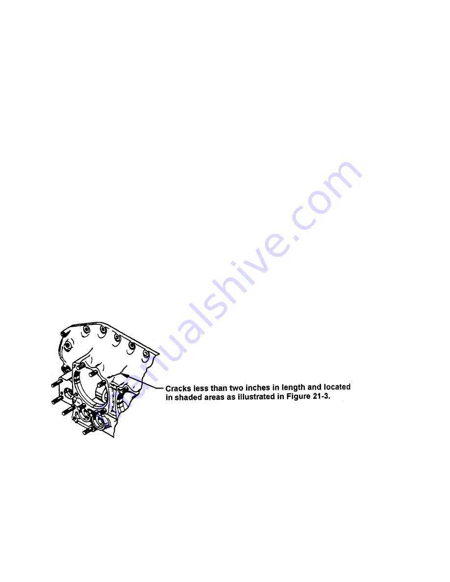
Critical (gray) and non-critical areas are illustrated in Figure 21-3. If a crack is observed in
any of the non-critical (dark gray) areas that is less than two (2) inches in length, the crack
should be scribe marked at its extremities and re-inspected for crack progression at the next
50 hours of operation. If no progression is observed and no additional cracks are found,
continue to inspect at regular intervals not to exceed 100 hours duration.
If a crack is observed in any non-critical (dark gray) areas that is more than two (2) inches in
length, or if a previously observed crack has progressed to two (2) or more inches in length,
repair or replace the crankcase prior to further flight. If any crack is observed in a critical
(gray) area, repair or replace the crankcase or engine prior to further flight.
Reasons for crankcase replacement:
A. Any crack in the critical (gray) areas.
B. Any crack two (2) inches or more in length in the non-critical (dark gray) area.
C. Any crack that is leaking oil (not seeping).
FIGURE 21-2. INSPECTION OF CRANKCASE NON CRITICAL AREA
Summary of Contents for CONTINENTAL L/TSIO-360-RB
Page 8: ...tNTENTIONALLY LEFT BLANK viii OCTOBER 1998 ...
Page 10: ...1 2 Change 2 INTENTIONALLY LEFT BLANK ...
Page 16: ...1 8 Change 2 Figure 1 1 L TSIO 360 RB Top and Front View ...
Page 17: ...1 9 Change 2 Figure 1 2 L TSIO 360 RB Side and Aft View ...
Page 20: ...1 12 Change 2 INTENTIONALLY LEFT BLANK ...
Page 27: ...3 1 CHAPTER 3 SEALANTS AND LUBRICANTS Sealants Lubricants 3 2 ...
Page 34: ...4 2 INTENTIONALLY LEFT BLANK ...
Page 56: ...INTENTIONALLY LEFT BLANK ...
Page 60: ...6 6 FIGURE 6 1 INSTALLATION DRAWING ...
Page 61: ...6 7 FIGURE 6 1 INSTALLATION DRAWING cont d ...
Page 62: ...6 8 FIGURE 6 1 INSTALLATION DRAWING cont d ...
Page 66: ...6 12 INTENTIONALLY LEFT BLANK ...
Page 72: ...7 6 INTENTIONALLY LEFT BLANK ...
Page 84: ...10 2 INTENTIONALLY LEFT BLANK ...
Page 87: ...11 3 FIGURE 11 1 INDUCTION AND EXHAUST SYSTEM ...
Page 96: ...INTENTIONALLY LEFT BLANK ...
Page 112: ...12 16 INTENTIONALLY LEFT BLANK ...
Page 126: ...INTENTIONALLY LEFT BLANK ...
Page 130: ...INTENTIONALLY LEFT BLANK ...
Page 134: ...INTENTIONALLY LEFT BLANK ...
Page 141: ...17 7 FIGURE 17 4 STARTER ADAPTER FITS LIMITS ...
Page 142: ...17 8 INTENTIONALLY LEFT BLANK ...
Page 145: ...OIL SUCTION OIL FILTERADAPTER SCREEN BOSS MOUNT FLANGE FIGURE 18 1 ACCESSORY CASE DESCRIPTION ...
Page 149: ...19 3 FIGURE 19 1 LUBRICATION SYSTEM SCHEMATIC ...
Page 151: ...19 5 ACCESSORY CASE INTERNAL VIEW TSIO 360 FIGURE 19 2 OIL PUMP DESCRIPTION TSIO 360 ...
Page 152: ...19 6 ACCESSORY CASE INTERNAL VIEW LTSIO 360 FIGURE 19 3 OIL PUMP DESCRIPTION LTSIO 360 ...
Page 160: ...19 14 INTENTIONALLY LEFT BLANK ...
Page 179: ...OCTOBER 1998 20 1 g ...
Page 183: ...21 3 FIGURE 21 1 CRANKCASE DESCRIPTION ...
Page 188: ...1NTENTIONALLY LEFT BLANK ...
Page 196: ...INTENTIONALLY LEFT BLANK ...
Page 205: ...23 9 FIGURE 23 6 CONSTANT SPEED SEA LEVEL PERFORMANCE CURVE ...
Page 206: ...23 10 FIGURE 23 7 FUEL FLOW VS METERED FUEL PRESSURE ...
Page 207: ...23 11 FIGURE 23 8 FUEL FLOW VS BRAKE HORSEPOWER ...


