background image

CHAPTER 2. PRECAUTIONS OF OPERATION 

2-1 Attention 

◎ 

Please  carefully  read  the  manual  before  installing  and  operating  this 
device. 

◎ 

Due to the complex nature of this equipment it is necessary to read the 
entire manual before installation. 

◎ 

Never  dismantle  the  equipment  by  any  unauthorized  personnel,  or 
equipment may be damaged. 

◎ 

This manual is for reference only. Pleases consult your distributor for 
further assistance. 

◎ 

The equipment has been strictly tested for quality before delivery from 
our  plant.  However,  this  equipment  must  not  be  used  in  dangerous 
situations or where damage may result. 

◎ 

After operation, shut off main power to the crane, power to receiver, 
and remove transmitter key. 

◎ 

Transmitter should be placed in a safe area  when not  in use to avoid 
accidental pressing of buttons. 

◎ 

The crane should be equipped with main power relay, limit switch and 
other safety devices. 

◎ 

Don’t use equipment during  lightening or high electrical interference 
conditions. 

◎ 

Make  sure  that  the  batteries  are  in  good  condition  and  power  for 
receiver is correct. 

◎ 

Maintenance should only be done while the crane’s main power is off 
to prevent electrical shock. 

◎ 

The  contents  of  this  manual  may  be  amended  by  the  manufacturer 
without notice. 

◎ 

The  manufacturer  may  introduce  new  functions  to  the  equipment  as 
necessary; therefore, the descriptions may change. 


2-2 Precautions 

◎ 

Operating  in  an  industrial  facility  is  relatively  dangerous;  therefore, 
operator  must  have  taken  the  adequate  trainings  in  using  F21-E2 
system. 

◎ 

Those  who  operate  the  machine  should  be  healthy  and  have  good 
judgment in regard to safety. 

Summary of Contents for F21-E2

Page 1: ...F21 E2 Industrial Radio Remote Controller Installation Operation Manual Lee s Hi tech Enterprise Co Ltd 2012 1 5 ...

Page 2: ... is used as a reference of F21 E2 remote There are two parts for different users operator and technician To avoid any unexpected machine or person accident or harm occurs before installation start up and operation please read carefully through the manual and follow the regulation and requirement ...

Page 3: ...truction manual for additional information High Voltage Indicates presence of hazardous voltage Unsafe practice could result in severe personal injury Ground connection For safety concern it is obligated to have ground connection Warning Denotes a hazard Included text gives proper procedures Failure to follow instructions could result in severe personal injury and or property damage Caution Denote...

Page 4: ...g red light 10 5 3 3 Constant red light 10 PART TWO TECHNICIAN S MANUAL 11 CHAPTER 1 GENERAL CHARACTERISTIC 11 1 1 General Specifications 11 1 2 Transmitter Specifications 11 1 3 Receiver Specifications 11 CHAPTER 2 INSTALLATION AND FUNCTION SETTING 11 2 1 Precautions during installation 11 2 2 Transmitter installation instructions 12 2 3 Receiver Installation Instructions 12 2 3 1 Preparation for...

Page 5: ...3 4 2 Multiple e Card copy procedure 19 ANNEX GLOSSARY OF FUNCTION SETTING 20 ...

Page 6: ...uct must be returned to a service facility designated by TELECRANE Buyer will pay shipping charges to TELECRANE while TELECRANE will pay return shipping charges 1 3 Excluded Items This warranty does not include consumptive parts such as batteries fuses buttons and relays Also this warranty does not cover defects caused by improper installation improper or insufficient maintenance unauthorized modi...

Page 7: ...smitter should be placed in a safe area when not in use to avoid accidental pressing of buttons The crane should be equipped with main power relay limit switch and other safety devices Don t use equipment during lightening or high electrical interference conditions Make sure that the batteries are in good condition and power for receiver is correct Maintenance should only be done while the crane s...

Page 8: ...flash in red constantly At this moment the batteries need to be replaced and all of four batteries should be replaced at the same time If the severe interference occurred the equipment should be stopped at once Please take the batteries out when the equipment will not be used for a long time Be sure to know the Procedures of Emergency as follows 2 3 Procedures of emergency In case of an Emergency ...

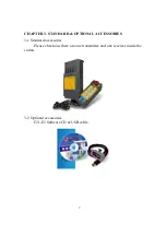
Page 9: ...7 CHAPTER 3 STANDARD OPTIONAL ACCESSORIES 3 1 Standard accessories Please check out there are one transmitter and one receiver inside the carton 3 2 Optional accessories F21 E2 Software CD USB cable ...

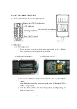
Page 10: ...t on its position 2 Put two AA batteries on the release ribbon And lock the battery cover Note Before placing the batteries make sure the Rotary KEY is on the OFF position 3 Turn the Rotary KEY into START position Or by setting the mode of power on e card on the transmitter Receiver wiring diagram Emergency STOP pushbutton LED Indicator Rotary KEY switch e card on the receiver Motion pushbutton ...

Page 11: ...eiver due to insufficient power Operator should avoid this situation in order to maintain the safety of operation CHAPTER 5 ROUTINE INSPECTION AND TROUBLESHOOTING 5 1 Routine inspection Daily inspection is important and will ensure the safety of operation Inspection should include emergency stop and other safety devices and functions If there is any doubt operation must be stopped immediately and ...

Page 12: ...tter back to normal stage Please re run the boot process again 5 3 2 Slow flashing red light The batteries are running out please install new ones 5 3 3 Constant red light Please check out the e card is on its position or not ...

Page 13: ... Power Supply 24 48 48 110 48 220 110 220 220 380 VAC 50 60 Hz 12 24 VDC multiple choice available Dimensions 190x85x62mm Weight 950g including RX cable CHAPTER 2 INSTALLATION AND FUNCTION SETTING 2 1 Precautions during installation Observe all safety precautions when climbing the crane To avoid electric shock please turn off the main power source of cranes before installation When installing the ...

Page 14: ...cap on the bottom of the transmitter 2 3 Receiver Installation Instructions 2 3 1 Preparation for Installation 1 Provide all necessary tools 2 Select a proper location a Select a stable place b Select a place where you can see the Receiver or Antenna c Select a place where there is no spark e g keep away from motors relays magnetic switch and power cables d Keep away from high voltage wiring and d...

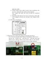
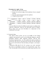
Page 15: ...receiver and crane so that cable cover wrapper will not wear out due to the vibration of the crane 2 3 3 Receiver wiring diagram 2 4 Receiver power transformer voltage selection and conversion F21 E2 receiver provides with 5 kinds of Transformer 24V 48 VAC 48 110 VAC 48 220 VAC 110V 220 VAC 220V 380 VAC that allows user to choose based on the power input on site and the designated voltage will be ...

Page 16: ...d Please check with your local distributor for replacement of the transformer if necessary 2 5 Function Setting This remote control system can be set according to the working condition and operator s need for the following purposes specific pushbutton function EMS neglected function Auto off time interference neglected time etc This enables the remote controller to perform the most effective opera...

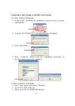
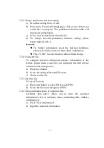
Page 17: ...ll be executed automatically Press the F21 E2 SETUP icon and continue the installation Press OK button Press Continue button and the installation procedure of F21 E2 software program is completed 3 2 How to start F21 E2 program Press Start button and choose Program Select F21 E2 PC Software Then select F21 E2 SETUP PROGRAM ...

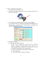
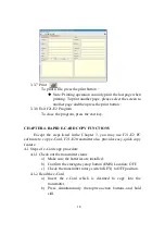
Page 18: ...f not installed please go back to the F21 E2 software installation and choose USB DRIVER INSTALL Read function setting 3 3 2 Write the new settings to e Card Use the F21 E2 software to read write e Card please be patient to complete the implementation of the software To avoid unexpected data corruption do not pull out the e Card or USB cable when perform read write procedure a Put the e Card into ...

Page 19: ...Press EXIT to close function table without change 3 3 4 Saving the file To complete function setting and customer information of the remote please make a copy on your computer for after service and future data management a Press Save button b Select the saving folder and file name c Then save the file 3 3 5 Open the file To open file data a Press open button or select FILE and OPEN b Select the fi...

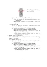
Page 20: ...Except the steps listed in the Chapter 3 you may use F21 E2 PC software to copy e Card F21 E2 transmitter also provides easy quick copy feature 4 1 Steps of e Card copy procedure 4 1 1 Check out the transmitter status a Make sure the batteries are installed b Confirm the emergency stop button EMS Location OFF c Check the transmitter rotary switch KEY to OFF position 4 1 2 Read the e Card a Insert ...

Page 21: ...the procedure from the beginning After the copy action is ending Return the rotary key switch KEY to OFF position 4 2 Multiple e Card copy procedure 4 2 1 and 4 2 2 Check and Read procedure are the same as the steps above 4 1 1 4 1 2 4 2 3 Multiple e Card copy a Put a blank or data can be overwritten e Card into the transmitter b Turn the rotary switch KEY to START position Green LED blinking Writ...

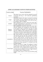
Page 22: ...hen press the Magnetic OFF pushbutton in the meantime The purpose is to prevent the operator from accidentally pressing the Magnetic OFF pushbutton and dropping the load held by the magnetic sucking disc ON OFF ON This function will set up a pair of buttons to control two relay outputs When the first relay turns on if you need to change into the second relay turns on then this setting will be forc...

Page 23: ...terval between acceleration relay i e conduction delayed time of acceleration relay It is suitable for accelerative operation only in order to prevent the cranes directly runs to highest speed to damage the motor Two speed Control Through the software setting F21 E2 remote controller allows to use A and B two single speed buttons to proceed two speed simulation control In this way the flexibility ...

Page 24: ...under continuous transmitting mode Auto OFF TX This function refers to turn off the Transmitter after a given idle time while transmitting the signal to switch off the receiver main relay Only available under continuous transmitting mode LED OFF Time This setting allows you to select the LED intermittent time to save transmitter power i e If 1 second is selected the LED will be lighted every 1 sec...

Page 25: ...ange exceeds the maximum remote control distances or the remote has been disturbed more than 0 5 seconds AUTO OFF RX This function refers to turn off receiver after a given idle time Receiver MAIN relay will be turned off automatically Normally this function is cooperated with non continuous transmitting mode to prevent any unintentional radio Channel setting Operating frequency of your remote con...

Reviews: