


6
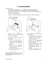
eClock Installation
2.
Pull a CAT5 Ethernet cable through
the knockout of the backbox.
3.
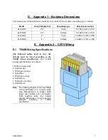
Terminate the end of the CAT5
Ethernet cable pulled through the
backbox.
The cable must be
terminated according to T568B
wiring specifications
. Refer to
Appendix 2 – CAT5 Wiring
.
1
4.
Remove the red plastic lens from the
eClock chassis by inserting a
flathead screwdriver into the tabs on
the side of the lines. Carefully twist
the screwdriver to snap each tab out
of the clock chassis. 4" eClocks have
a #4 x 5/8" self-tap locking screw on
the top or bottom edge of the lens
that must be removed before
removing the releasing the tabs.
5.
Plug the CAT5 Ethernet cable to the
eClock Ethernet port.
6.
Carefully mount the eClock onto the
installed backbox using the four #8 x
1" screws.
1
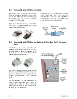
After terminating the CAT5 Ethernet cable, ensure that it is
wired properly by using a RJ45 cable tester before
connecting the cable to the eClock and PoE network switch.
If desired, the CAT5 Ethernet cable can be terminated using
a toolless keystone jack inside the backbox for easier wiring.
Refer to
Appendix 2 – CAT5 Wiring
.
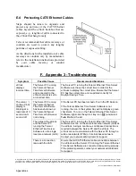
If the CAT5 Ethernet cable running outside the backbox is
exposed, steps should be taken to protect the cable using
cable raceways or conduits. Refer to
Appendix 2 – CAT5
Wiring
.
7.
Replace the plastic lens over the
eClock chassis and snap it into place.
Ensure that the paper framing insert
is inside the lens. For 4" eClocks,
secure the lens to the clock chassis
using the #4 x 5/8" self-tap locking
screw.
8.
Terminate the other end of the CAT5
Ethernet cable.
The cable must be
terminated according to T568B
wiring specifications.
Refer to
Appendix 2 – CAT5 Wiring.
Plug the
cable to the PoE network switch. The
eClock will power up, perform a
display testing sequence, and then
display the time.
2
9.
Repeat steps 1 through 8 for each
eClock in the facility.
2
The PoE network switch must be able to support maximum
power for each eClock connected to it. Each port on the
switch must support IEEE 802.3af with a maximum power of
15.4W (12.95W at the eClock).


