background image


Installation tips


Vers. 001


Flat Sat Light


25 

Installation tips


1) The MIR remote control Extension must be installed in such a way as to make sure that 

it is always visible and that the remote control can therefore operate normally. 

2)  Do  not  install  the  Control  Unit  in  an  area  subject  to  liquid  spilling  which  could  cause 

irreparable damage to it. 

3)  Do  no  install  the  Control  Unit  in  too  small  a  space  with  poor  ventilation,  because 

excessive heat could alter its good operation 


Receiver installation 

Introduction 

To perform properly the receiver needs to be connected properly. If your receiver has been 
installed by a technician it will be ready for operation and you can go straight to the section 
on  “Immediate  use  of  the  receiver”.  If  you  are  installing  the  unit  yourself  follow  the 
instructions below. 

Main connections 

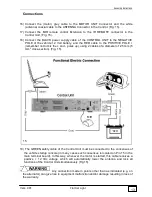
Connecting the lead from the satellite dish 

Connect the coaxial lead from the satellite dish using an F-connector on the input socket 
(1).  Make  sure  that  the  central  conductor  of  the  coaxial  lead  is  inserted  correctly  in  the 
receiver and is not bent or twisted. 

Connecting the SCART cable between the receiver and the TV or monitor 

Insert one end of the SCART cable in the socket (5) and connect the other end to the TV 
set. It is always best to use a complete SCART plug (i.e. one with 21 pins); doing so allows 
you  to  use  RGB  mode  (where  the  TV  set  has  this  feature),  which  gives  better  image 
quality.  If  your  TV  set  does  not  have  a  SCART  connection  (or  a  base  band  audio/video 
input), the receiver can be connected with the modulator as described below. 

Connecting the coaxial cable between receiver and TV 

Insert the coaxial cable in the socket (8) and connect the other end to the TV antenna. If 
you  have  an  antenna  for  reception  of  terrestrial  TV  signals  it  can  be  connected  to  the 
antenna input socket (9). In this case it is necessary to ensure that the output channel set 
on  the  receiver  (between  channel  21  and  channel  69)  is  free  from  any  terrestrial  TV 
antenna interference. 

Connecting the remote control infrared sensor 

All  receiver  functions  can  be  controlled  via  the  remote  control.  The  remote  control  emits 
infrared signals that are captured by a remote sensor supplied with the receiver. Position 
the  remote  infrared  sensor  within  view  of  the  remote  control  unit  (e.g.  near  the  TV).  The 
remote infrared sensor has an adhesive base so that it can be installed where desired. 
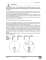
Warning:  do  NOT  install  the  remote  infrared  sensor  near  fluorescent  lighting  or  strong 
electrical fields as they can reduce the capacity of the sensor to capture signals emitted by 
the remote control. 


Summary of Contents for Flat Sat Classic Smart 85

Page 1: ...Vers 001 INSTALLATION GUIDE AND USER MANUAL OF THE FLAT SAT LIGHT GB...

Page 2: ...Flat Sat Light Operation System 16 Satellite seeking 16 Programme seeking 16 Antenna lowering 16 Additional operations 17 Changing satellites during search 17 Safety function 17 Important information...

Page 3: ...ns 31 Introduction 31 Accessing the menu 31 The favourites list 32 Creating a list 32 Modifying a list 34 Deleting a list 37 Installation 37 Antenna Satellite configuration 38 LNB configuration 44 Mot...

Page 4: ...2008 Document version 001 Software revision 2 4 Should you require further information please contact your local dealer or TELECO s p a Via E Majorana 49 I 48022 LUGO RA Web site www telecogroup com...

Page 5: ...Working frequency 950 2150 MHz Rated input impedance 75 Acceptable signal level from 25 to 65 dBm DiSEqC control version 1 0 and 1 2 QPSK modulation Symbol rate from 2 to 31 Ms s FEC from 1 2 to 7 8 M...

Page 6: ...een specially made to protect it from knocks and pressure The following accessories are supplied 1 External motor driven unit 2 65 85 cm dish 3 Universal LNB 3 SKEW OPTIONAL 4 Control unit receiver 5...

Page 7: ...ontrol unit b the second item only contains the dish It is essential to check that the dish has not been damaged during transport when the package is opened In particular check the following well By r...

Page 8: ...dish to the mast and screw down the four supplied screws 6 Press the DOWN button in the remote control and lower the antenna 7 Disconnect the Control unit the battery and install Flat Sat Light on the...

Page 9: ...late as Fig 4 with the short side towards the driving direction of the vehicle Fig 4 7 Clean the lower part of the BASE PLATE carefully applying a layer of glue on the whole surface e g SIKAFLEX 8 Fas...

Page 10: ...hrough the middle of the base 10 Connect the Grey and White cables coming from inside the vehicle Fig 6 to both cables of the outside unit making them watertight using two pieces of THERMORETRACTILE T...

Page 11: ...n the plate bearing in mind that a The proper position must be as in Fig 9 b Coat both the base plate and the driving unit bottom Fig 10 with a thick layer of silicone to prevent any water infiltratio...

Page 12: ...ng this operation do not pull either cable forcibly as they could come out 13 Connect both cables coming from the centre of the OUTSIDE UNIT to the extensions Waterproof the connectors using both piec...

Page 13: ...member not to mix the and poles up using 2 cables of a diameter of 2 5 mm 5 mm2 cross section Fig 15 19 The GREEN safety cable of the Control Unit must be connected to the consensus of the vehicle sta...

Page 14: ...ne end of the SCART cable in the TV connector of the Control Unit and connect the other end to the TV set Fig 16 21 Inside the Control Unit are a Control ELECTRONICS of the outdoor unit motors b DVB D...

Page 15: ...fore checking its operation we suggest you make sure that The outside converter also called LNB has been installed properly and locked into its plastic lock nut Remember that the outside converter has...

Page 16: ...e control or select it from the program list Flat Sat Light will then search for the next satellite and store the corresponding antenna position Antenna lowering When Flat Sat Light is on antenna is u...

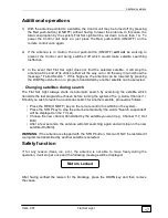
Page 17: ...ellite can be selected Changing satellites during search The Flat Sat Light always starts its automatic search by examining the satellite which transmits the last programme chosen before turning the s...

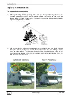
Page 18: ...ouses etc This way the antenna will be free to receive signals coming from the satellite 2 It is also important to know that satellites do not transmit with the same intensity throughout Europe so if...

Page 19: ...ts avoid using low quality non stabilized battery feeders Trouble shooting If the Flat Sat Light has not found the satellite after a complete search check the following a Is the view towards the South...

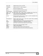
Page 20: ...t Sat Light Vers 001 20 DIGITAL RECEIVER BUILT IN THE CONTROL UNIT Remote Control ON OFF Mute EPG TV RADIO Right left up down and OK keys Menu Page Exit Audio FAV Favourites list Info Pause DOWN STOP...

Page 21: ...xits the previously selected page Audio Chooses which audio service to listen to if the broadcaster has activated the multi audio service Favourites list Selects which service list to use from among t...

Page 22: ...Figure 1 frontal panel Rear view Figure 2 rear panel On off CAM modules 2 LNB input 1 LNB output 2 VCR 4 Audio outputs 7 Computer port 3 TV 5 S VHS 6 Power supply 12V 12 DataPort 11 IR Remote 10 TV o...

Page 23: ...connector in S VHS Audio outputs Auxiliary audio output connectors L R connectors are available as is a S PDIF connector for PCM Digital format audio output Antenna input Traditional VHF UHF band ant...

Page 24: ...be removed for maintenance and set up purposes and only after taking all the required precautions Before removing the electronic device covers always check that the mains power supply is OFF and that...

Page 25: ...socket 5 and connect the other end to the TV set It is always best to use a complete SCART plug i e one with 21 pins doing so allows you to use RGB mode where the TV set has this feature which gives b...

Page 26: ...Connecting to a video recorder Insert the SCART cable in the socket 4 of the receiver labelled VCR This allows you to record the selected service on tape or play a VHS cassette Connecting to a monitor...

Page 27: ...control When you press the ON OFF key on the remote control the receiver comes on and the frontal display shows the legend ON followed by the previously selected service if this is the first time the...

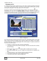
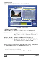
Page 28: ...he main menu MENU key Figure 4 Camping menu The current program is shown in the window at left Two other fields appear the top right field is used to select the desired service while the field at the...

Page 29: ...l area it is therefore intended for such area These lists are in every respect a first customization of the receiver which can easily be removed by the user As such it CANNOT be restored any more if t...

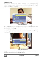
Page 30: ...info function Press the EPG key to view comments where available or use the keys to select information on the event in progress the first or the next one the second Per uscire premere il tasto EXIT A...

Page 31: ...sts or the key receiver settings you will need to access the advanced functions Important note that modifying the technical parameters of your receiver can cause malfunctions and or data loss Always p...

Page 32: ...rites lists see next para Creating a list After selecting this item and pressing the OK key you will enter the menu as shown in fig 11 Key in the name of the list in the suitable field via the numeric...

Page 33: ...the Radio services Encoding mode All the list will consist of all the services picked up by the receiver Coded the list will only consist of the services for which the Network or Broadcaster provided...

Page 34: ...t of all services independently of the broacasting satellite NAME of the satellite the list will only consist of the services which are broadcast by the selected satellite Once the name has been defin...

Page 35: ...llows you to lock unlock any selected service by pressing the OK key You must key in the PIN code to access any locked service for entering or modifying the PIN code and for enabling disabling the set...

Page 36: ...low key and press OK to confirm Then select pos 6 press the Yellow key and press OK to confirm Network ID Blue key the services in the list are arranged by Network ID Satellite ID Green key the order...

Page 37: ...overed any more except for the TV and Radio lists which cannot be deleted but only emptied Installation This sub menu allows you to set all the main functions of your receiver Note these settings are...

Page 38: ...uration This sub menu indicates the type of equipment and or connection between your receiver and the satellite dish Once this sub menu has been selected it gives access to further sub menus Figure 15...

Page 39: ...connection with motorised systems based on the DiSEqC protocol MagicSat i e connection to the motorised TELECO MagicSat system Select an item using the keys and confirm your choice by pressing the OK...

Page 40: ...satellites The available options are Add a new satellite to the general satellite list Modify the satellite list i e modify the technical information of each satellite Remove a satellite from the lis...

Page 41: ...atellite orientation i e Eastwards or Westwards Frequency of reference transponder Polarisation emitted for the above transponder frequency Symbol rat FEC ID transponder Select an item using the and n...

Page 42: ...using the keys and confirm your choice by pressing the OK key To leave the menu press the EXIT key Deleting a satellite From this sub menu you can remove a satellite The list of satellites is propose...

Page 43: ...tellite You can select each of these items via the and numerical keys confirm your choice via the OK key and exit this menu via the EXIT key Deleting a transponder Use this sub menu to delete a transp...

Page 44: ...witch from low to high band Band type Ku or C As a general rule these fields need not be modified as the LNB converters marketed in Europe are of the UNIVERSAL type and are defined inside the receiver...

Page 45: ...uctions provided by the makers Select an item using the up down keys and confirm your choice by pressing the OK key To leave the menu press the EXIT key MagicSat Configuration The receiver stores in m...

Page 46: ...plete scan of the satellite band Download the current service list is sent to a computer connected to the serial port Upload a list of services is sent from the computer towards the receiver using the...

Page 47: ...Menu and advanced functions Vers 001 Flat Sat Light 47 Figure 277 Service acquisition Once the scan has been completed the following message appears Figure 288 Service acquisition over...

Page 48: ...al confirmation message Figure 299 Services saved on the receiver TV configuration Use this sub menu to set the receiver TV connection specifications Figure 30 TV Configuration To reach this screen pa...

Page 49: ...key To leave the menu press the EXIT key Set time Use this sub menu to set the clock on your receiver Figure 31 Setting the clock The available fields are Mode i e whether the time is controlled via...

Page 50: ...using the keys and confirm your choice by pressing the OK key To leave the menu press the EXIT key Reinstallation The reinstallation procedure consists of cancelling all the information on your recei...

Page 51: ...r Symbol rate of the transponder FEC of the transponder These parameters are generally preset to the correct values yet can at TELECO s request be adapted to carry out any updates Select an item using...

Page 52: ...yed by your Flat Sat Light receiver and the default audio language If the received service is available in the default language this language will be selected automatically If it is not your receiver...

Page 53: ...e unlocked by the user it should be returned to the factory for technical servicing Note the PIN code is factory set to 1234 Figure 36 Controlling access to receiver functions Modifying the PIN code U...

Page 54: ...cess This sub menu provides information and instructions for reception of services requiring payment CA Controlled Access These are managed via the CAM Control Access Module which must be inserted in...

Page 55: ...ess to CAM information Select an item to obtain more detailed information on the technical specifications of the inserted CAM and on the subscription to the card in the module this information changes...

Page 56: ...nctions Flat Sat Light Vers 001 56 There follow some examples of additional information relative to the inserted CAM and card Figure 41 Example of information on the CAM Figure 42 Example of informati...

Page 57: ...s to be fully deleted Re installation sequence To re initialize your receiver select the main menu via the MENU key on the remote control and choose the Re installation command from the Installation i...

Page 58: ...OK key and the following appears Figure 45 Setting the language during re initialisation Set the desired language with the right and left arrow keys then confirm with the OK key Then set the type of T...

Page 59: ...the service installation mode Figura 48 Service installation Once this task has been completed confirm with the OK key At this point your receiver will start acquiring the service list for the reques...

Page 60: ...Reinstalling your receiver Flat Sat Light Vers 001 60 Figure 49 Services being installed Figure 50 Service reception complete Figure 51 Services saved...

Page 61: ...requested to set the clock on your receiver Figure 52 Clock setting Unless specifically stated otherwise it is advisable to leave the settings in automatic At the end press the OK key again to confir...

Page 62: ...r Broadcaster refers to the company supplying the service within one or more bouquets Transponder The term transponder refers to a satellite transmission service On previous analogue systems a transpo...

Page 63: ...Flat Sat Light digital Tav 1 Vers 1 del 10 02 2009...

Page 64: ...zo LNB 50 65 11 10532 N 1 Inserto sinistro per braccio LNB 85 LNB mast left hand insert 85 Partie intercalaire gauche pour bras LNB 85 Linker Einsatz f r LNB Arm 85 Linker inzetstuk voor LNB arm 85 In...

Page 65: ...Flat Sat Light digital Tav 2 Vers 1 del 10 02 2009...

Page 66: ...x1 5 55 11077 N 1 Ruota dentata Dinterno 30 Denti 40 Gearwheel Inside dia 30 Teeth 40 Roue dent e interne 30 Dents 40 Zahnrad Di 30 Z hnezahl 40 Tandwiel inw diam 30 tanden 40 Rueda dentada interior 3...

Page 67: ...77 06817 N 2 Rondella piana D 3 UNI6592 zinc Flat washer D 3 UNI6592 galvanized Rondelle plate D 3 UNI6592 zingu e Scheibe flach D 3 UNI6592 verzinkt Onderlegring plat D 3 UNI6592 verzinkt Arandela pl...

Page 68: ...Flat Sat Light digital Tav 3 Vers 1 del 10 02 2009...

Page 69: ...TTORE R91 R91 Switch Commutateur R91 Schalter R91 Schakelaar R91 Interruptor R91 8 09835 N 4 Piedino nero in gomma Black rubber foot Pied noir en caoutchouc Schwarzer Gummifu Zwart rubber pootje Pie n...

Page 70: ...Flat Sat Light digital Tav 4 Vers 1 del 10 02 2009...

Page 71: ...INTOP PG21 Kunststoffmutter SKINTOP PG21 Moer plastic SKINTOP PG21 Tuerca pl stico SKINTOP PG21 10 06219 N 1 Cavo SCART VC3DL 1 5 M SCART CABLE VC3DL 1 5 m C ble P ritel VC3DL 1 5 m SCART Kabel VC3DL...

Page 72: ...eco telair bleysetd com Service Technique France 06 83 31 44 05 ESPA A NAUCCA CARAVANING S A Poligono Industrial CAN ROQUETA 2 Calle Can Lletget 2 08202 Sabadell Barcelona Espa a Tel 00 34 937 457 054...

Reviews: