


Telecast
Operating Details
9
Operating Details
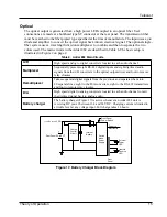
Battery Charging
Charge the internal UPS batteries at a minimum 13.8 VDC for 16 hours (40 mA trickle charge) by
attaching each unit to its external power supply. This will permit battery operation for up to
20 minutes during line power losses.
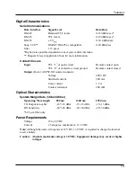
Indicators
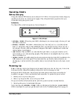
The three LEDs on the front panel are shown in Figure 11.
Figure 11. Front Panel
¥
EXTERNAL
POWER
.
When this green LED is illuminated, an external supply of between 12 and
24 VDC is connected.
¥
INTERNAL
RESERVE
.
This LED is illuminated green when the power is on and the internal
battery is adequately charged. This LED lights after one half hour of charge. There may be a
few minutes of reserve after the indicators extinguish. This LED is illuminated red when the
internal battery is discharging.
¥
LINK
STATUS
.
This red LED is on when the Þber optic link is
not
properly attached, or the
system units are
not
communicating properly. This indicator is meaningful only if one of the
other two LEDs is on.
¥
AUDIBLE
ALARM
.
An audible alarm has been incorporated into the Adder 882 in addition to the
LED indicators on the front panel. This alarm alerts the user that the internal batteries are
discharging. A defeat switch for the audible alarm is located inside the unit on the main circuit
board.
Powering Up
Note:
A locking switch is provided to prevent inadvertent power turn off. Never try to move the
front panel switch without Þrst pulling on the switch lever to disengage its lock.
With power OFF at both units, check all electrical and optical connections as described in
Installation
on page 3. Firmly seat and latch all connectors. To operate the power switch:
1. Pull the lever away from the panel.
2. Move it
up
for power ON, or
down
for power OFF.
The power switches at both units must be on for the system to achieve normal function.
3. Switch on the power to both Adder 882 units.
Verify that the green
EXTERNAL
POWER
LEDs
are illuminated, and that the red
LINK
STATUS
LEDs do not light. If you do not get this result, refer to the Troubleshooting Chart on page 16.
POWER
ADDER 882
ä
AUDIO/DATA MUX/DEMUX
Fiber Systems, Inc.
Te l e c a s t
INTERNAL
RESERVE
LINK STATUS
EXTERNAL
POWER
ON
OFF


