background image


www.tekvox.com 

1201-N+ 

79033-N+ User Manual 
 

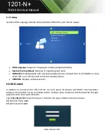
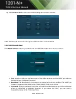
5.8.2 Configuration Menu 

1) 

Click 

 on control menu to enter setting menu shown as below: 


Output Resolution

: Select the output resolution that you need and then click Confirm. 


Update

: Insert the USB flash drive with EDID file/software updating the file to FIRMWARE 

port, and then click EDID/Firmware to start the update procedure. 


Shutdown Timer (NO Input)

: Set the shutdown time under manual-switching mode or auto-

switching  mode  including  none,  1  minute,  2  minutes,  5  minutes,  and  10  Minutes.  If  the 
Switcher cannot detect a video source input, it will automatically shut down after a preset 
interval. 

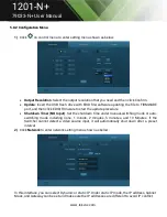
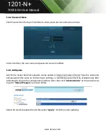
2) 

Click 

Network

 to enter network setting menu shown as below: 

 
In this interface, you can select Dynamic or static IP. Under static IP mode, the IP address, Subnet 
Mask, and Gateway can be set and make sure the IP addresses are different to avoid IP conflict. 

Summary of Contents for TEK 1201-N+

Page 1: ...www tekvox com 1201 N 79033 N User Manual 1201 N Seamless Presentation Switcher All Rights Reserved Version 79033 N _2020V1 0 ...

Page 2: ...ement This equipment generates uses and can radiate radio frequency energy and if not installed and used in accordance with the instructions may cause harmful interference to radio communications It has been tested and found to comply with the limits for a Class A digital device pursuant to part 15 of the FCC Rules These limits are designed to provide reasonable protection against harmful interfer...

Page 3: ...o rain moisture or install this product near water Do not put any heavy items on the product s power cable Do not remove the housing of the device as opening or removing housing may expose you to dangerous voltage or other hazards Install the device in a place with sufficient ventilation to avoid damage caused by overheating Keep the module away from liquids Spillage into the housing may result in...

Page 4: ...l 11 3 2 2 TPUH411RA Rear Panel 12 4 System Connection 13 4 1 Installation Precautions 13 4 2 System Diagram 13 4 3 Connection Procedure Steps 14 4 4 Connection of Microphone Mixer 14 4 5 Application 14 5 Front Panel Control 15 5 1 Manual Switching 15 5 2 Auto Switching 15 5 3 Volume Adjustment 15 5 4 Operations of IR 16 5 4 1 IR Remote 16 5 4 2 Control of Far End IR Device from Local 17 5 4 3 Con...

Page 5: ... Local and Remote 28 5 7 Operations in OSD Menu 29 5 7 1 Options 29 5 7 2 Instructions for VGA Converting Cable 30 5 7 3 Picture 32 5 7 4 Setup 33 5 8 GUI Control 33 5 8 1 Control Menu 34 5 8 2 Configuration Menu 35 5 8 3 RS232 Control Menu 36 5 8 4 Password Menu 37 5 8 5 GUI Update 37 6 Panel Drawing 38 7 Troubleshooting Maintenance 39 8 After Sales Service 40 ...

Page 6: ... Drop In commands Hands Free operation with automatic switching and power control of a display using CEC IR remote control from receiver IR pass through to receiver IR from receiver to sources On Screen Menu Controls for easy setup Control of HDMI sources with CEC or IR Control of display with CEC IR or RS232 Allows RS232 pass through for display control Rack and wall mounting kit included 1 1 Fea...

Page 7: ...IR receiver 1 x IR emitters 1 x RS232 cable 3 Pin phoenix connector to DB9 1 x VGA converting cables male VGA to female YPbPr 2 x 3 Pin phoenix connectors 1 x 5 Pin phoenix connector 6 x Screws black color 4 x Plastic cushions 1 x TEK TPUH411RA HDBaseT Receiver 1 x User Manual Note Please contact your distributor immediately if any damage or defect in the components is found ...

Page 8: ... video 150 MHz YPbPr 170 MHz VGA 375 MHz Transmission Distance 325 ft 100m HDCP Compliant w DVI HDMI 1 4 HDCP 2 2 Audio Input 1 Stereo Audio for VGA 3 5mm jack 1 Stereo Line Level 3 Pin Phoenix 2 Stereo Audio Input 3 5mm jack Audio Output 1 Balanced Stereo 5 Pin Phoenix Frequency Response 20Hz 20KHz Control IR Remote Front Panel Buttons RS 232 TCP IP Power Supply Input 100VAC 240VAC 50 60Hz Output...

Page 9: ...for OSD 7 5 HDMI input selector and activity LED ENTER key for OSD 8 6 VGA input selector and activity LED OSD menu button 9 Auto switching selector and activity LED Press this to enter or exit auto switching mode Long press this button 3 seconds or more to reset output resolution to 720p or to activate HDMI and HDBT outputs if they have been turned off Note When you set any VGA port to C video or...

Page 10: ... 2 AUDIO 3 5mm mini jack embedded audio input for 2 HDMI 4 CONTROL IR IN IR OUT Connect with IR Receiver and Emitter to control devices via IR IR EYE Connect with the IR Receiver with carrier wave only to control this SC61TS via the including IR Remote FIRMWARE Type A USB port for updating system firmware or loading customized EDID data RS232 Serial port 3 pin phoenix connector connect with a cont...

Page 11: ...232 port and then double click the update file bat UPDATE B Update the IC program which is used for de embedding audio The upgrade method is the same as the above UPDATE A 2 Link status LED OFF No Link GREEN Link successful 3 HDCP compliant LED OFF No HDMI traffic GREEN Traffic with HDCP Blinking GREEN Traffic without HDCP 4 Power LED RED when the device is powered on and no indicator when there i...

Page 12: ...to control input source device 4 HDMI OUT HDMI type A connector connects to display 5 AUDIO OUT 3 5mm stereo audio jack connects to analog stereo audio device 6 COAX OUT Coaxial audio connector connects to digital audio device 7 OPTICAL OUT Optical audio connector connects to optical audio devices 8 HDBT IN Connects to the HDBT OUT socket on HDBaseT Transmitter or Matrix Switcher via CAT5e 6a 7 ca...

Page 13: ...n environment with normal operating temperatures and humidity All of the power switches plugs sockets and power cords should be installed according to safety standards All cables should be properly terminated and tested before connecting to the unit All devices should be connected before powering the unit on 4 2 System Diagram ...

Page 14: ... IR signal can be transmitted bi directionally between the Scaler Switcher and the HDBaseT Receiver 10 Connect DC24V power adaptor to the power port HDBaseT Receiver can be powered by the Scaler Switcher with PoH function Note If the power adapter is connected to HDBaseT Receiver the Scaler Switcher can t be powered from the HDBaseT Receiver 4 4 Connection of Microphone Mixer The TEK 1201 N only p...

Page 15: ...er will automatically enter auto switching mode If the last displayed signal is still available the unit will output this signal If not the unit will detect all the input signals with priority from 1 HDMI to 6 VGA The first detected signal is sent to the output Signal removing When a signal is removed the unit will detect all the input signals with priority from 1 HDMI to 6 VGA The first detected ...

Page 16: ...utton is used to power cycle the switcher and CEC controlled display 2 Input Selection buttons 1 6 Select video source via the corresponding button 3 AUTO Enter Exit auto switching mode 4 MUTE Mute and unmute the audio 5 VOL Volume adjusting button Pressing this button displays the volume adjusting menu 6 Menu Operation Buttons OK confirm button UP DWON LEFT RIGHT button for value setting or page ...

Page 17: ...mitter to the IR OUT port on the HDBaseT Receiver The far end device can be control by its IR remote from local 5 4 3 Control Local Device from Remote Connect an IR emitter to IR OUT port on the Compact Scaler Switcher and connect IR receiver to the IR IN port on the HDBaseT Receiver The source devices can be controlled by their IR remote from the receiver ...

Page 18: ...ected HDMI input source device and display power on as well CEC on Standby off Press STANDBY button on IR remote The Switcher enters in standby mode HDMI 1 3 source devices and display do not change CEC on Use and buttons on IR remote to control HDMI source device CEC off Unable to control HDMI source device and display through IR remote 5 6 RS232 Control Use the RS232 port on the TEK 1201 N or HD...

Page 19: ... Enable auto switching 50682 CR LF 50786 Disable auto switching 50786 CR LF Audio Commands 50600 MUTE Source audio 50600 CR LF 50601 Un Mute Source audio 50601 CR LF 50602 Source audio volume up 501xx CR LF 50603 Source audio volume down 501xx CR LF 501xx Set the Source volume xx 00 to 60 501xx xx 00 60 50720 Mute Source audio MIC audio 50720 CR LF Mute 50721 CR LF Unmute 50721 Unmute Source audio...

Page 20: ...1024X768 XGA 50626 CR LF 50627 Set the output resolution to 1280X720 720P 50627 CR LF 50628 Set the output resolution to 1280X800 WXGA 50628 CR LF 50629 Set the output resolution to 1920X1080 1080P 50629 CR LF 50620 Set the output resolution to1920X1200 WUXGA 50620 CR LF 50621 Set the output resolution to1600X1200 UXGA 50621 CR LF 50624 Set the output resolution to 1600X900 50622 CR LF Setup Comma...

Page 21: ...ut 50758 CR LF 50759 Turn on HDMI HDBT output synchronously 50759 CR LF 50760 Turn on HDBT POH Power 50760 CR LF 50761 Turn off HDBT POH Power 50761 CR LF Adjustment Commands 50678 Enable screen output adjusting 50678 CR LF 50679 Disable screen output adjusting 50679 CR LF 50670 Move the image to right 50670 xx CR LF 50671 Move the image to left 50671 xx CR LF 50672 Move the image up 50672 xx CR L...

Page 22: ... 50910 Confirm command 50910 CR LF 50911 Exit command Toggle Menu 50911 CR LF 50912 Pause 50912 CR LF 50913 Power on input source device 50913 CR LF 50914 Power off input source device 50914 CR LF 50915 Enable input CEC auto power 50915 CR LF 50916 Disable input CEC auto power Do not allow the Switcher to power on from Blu ray being powered on 50916 CR LF 50917 Next chapter 50917 CR LF 50918 Previ...

Page 23: ...4 Set 4 HDMI EDID to 1080P 50744 CR LF 50745 Set 4 HDMI EDID to 1920x1200 50745 CR LF 50747 Set 5 HDMI EDID to 720P 50747 CR LF 50748 Set 5 HDMI EDID to 1080P 50748 CR LF 50749 Set 5 HDMI EDID to 1920x1200 50749 CR LF 50767 Restore default EDID 50767 CR LF 50768 Bypass EDID data from output to input 50768 CR LF 50769 Upload custom EDID data to the switcher 50769 CR LF 50782 EDID management copy th...

Page 24: ...0773 Manual Switch Mode Set the power off time to 2 minute 50773 CR LF 50774 Manual Switch Mode Set the power off time to 5 minute 50774 CR LF 50775 Manual Switch Mode Set the power off time to 10 minute 50775 CR LF Get Status 50754 Get the panel locked status 50604 CR LF 50605 CR LF 50719 Check the auto power off time 50714 50771 50772 50773 50774 50775 CR LF 50631 Get the input source xx HDMI1 H...

Page 25: ...Get the color temperature xx 01 Cool 02 Medium 03 Warm 04 User 50607 xx CR LF 50635 Get the image aspect ratio xx 01 16 9 02 4 3 03 auto 50608 xx CR LF 50633 Get the image mode xx 01 Dynamic 02 Standard 03 Mild 04 User 50614 xx CR LF 50753 Get the freeze status 50655 CR LF 50656 CR LF 50659 check input HDMI audio status 50660 50661 CR LF 50662 50663 CR LF 50664 50665 CR LF 50666 50667 CR LF 50668 ...

Page 26: ... LF Source Mute 50722 50723 CR LF Line Mute 50785 50786 CR LF Switching mode 50726 50727 CR LF VGA MUTE 50797 50697 CR LF Standby On TEKVOX Commands 521xx TekMonitor Macro Command xx 01 99 CMD 01 99 Note Turn on off HDCP auto management by sending serial commands When HDCP is set to active whether or not the output source has HDCP depends on the input source If the input source has HDCP the output...

Page 27: ...er TekMonitor serial control allows the TEK 1201 N to be controlled from both the local RS232 port on both the unit and the HDBaseT receiver 5 6 3 Control TEK 1201 N AND Display from Local RS232 Port This mode allows a 3rd party controller to send commands to both the TEK 1201 N and display device 1 Connect the RS232 port of TEK 1201 N to RS232 port of PC 2 Send the command 50787 via RS232 communi...

Page 28: ...ith a TekMonitor at the HDBaseT receiver 1 Connect the RS232 port of TEK 1201 N to RS232 port of PC 2 Send the command 50788 serial control mode 1 factory default via RS232 communication software 3 Send any control command for the TEK 1201 N from either RS232 port on unit or HDBaseT receiver Connection is shown below Control 1201 N using TEKVOX Equipment ...

Page 29: ... on IR remote Press the Menu 3s for three seconds or send command 50616 to enter in OSD menu Operation way Press on the IR remote to switch between menu options and menu pages Press on the IR remote to confirm the selection Press on the IR remote to exit OSD menu 5 7 1 Options Includes Output Adjust Input 6 Selection Baud rate User EDID Load USB Resolution Audio Mute Setup IP Address and Software ...

Page 30: ...x768 Audio Mute Setup Turn on off the Mix HDMI 1 HDMI 2 HDMI 3 HDMI 4 HDMI 5 VGA audio IP Shows the current IP address Software Update USB Insert the USB flash drive with updating file to USB port of the Scaler Switcher in order to update the software through this menu 5 7 2 Instructions for VGA Converting Cable VGA inputs support YPbPr and C video sources The TEK 1201 N comes with 1 VGA convertin...

Page 31: ...ons and OSD Press the MENU button on the front panel to enter into OSD and enter into the OPTION setting menu set INPUT 5 Select to AV Via RS232 commands Send command 50685 to switch to YPbPr source 2 Via IR remote OSD Press MENU button on IR remote to enter into OSD and in the OPTION setting menu set INPUT 5 Select to AV source B Connecting the VGA converting cable as pictured below ...

Page 32: ...Range Picture Mode Includes Dynamic Standard Mild and User User mode sets the image contrast brightness color and sharpness Color Temperature Includes Cool Medium Warm and User User mode sets values for Red Green and Blue RGB Aspect Ratio Includes Native 4 3 16 9 Zoom1 Zoom2 Just Scan and Panorama VGA format only supports 4 3 16 9 and Panorama ...

Page 33: ... Default CEC on STANDBY on Only when CEC is on will it be able to set auto standby status VERSION Displays software version 5 8 GUI Control In addition to control of the TEK 1201 N via front panel IR remote and RS232 communication software the Switcher can be controlled via GUI It allows users to interact with the Switcher through graphical icons and visual indicators Type 192 168 0 178 into your ...

Page 34: ... this button to adjust the position of VGA video output image to ensure the best visual effect Display Click this button to turn on off the output display device Standby Click this button to put the Scaler Switcher in standby mode Embedded Audio Click 1 Audio to select embedded audio for 1 HDMI input and click 2 Audio to select embedded audio for 2 HDMI input Volume Click the corresponding positiv...

Page 35: ...tart the update procedure Shutdown Timer NO Input Set the shutdown time under manual switching mode or auto switching mode including none 1 minute 2 minutes 5 minutes and 10 Minutes If the Switcher cannot detect a video source input it will automatically shut down after a preset interval 2 Click Network to enter network setting menu shown as below In this interface you can select Dynamic or static...

Page 36: ...hown as below Port Local port refers to the RS232 port of the Scaler Switcher and the HDBT port refers to the RS232 port of HDBaseT Receiver Baud Rate The baud rate of the local port is 9600 which can t be modified The HDBT por however supports 2400 4800 9600 19200 38400 57600 and 115200 Command Typing commands in this box controls the Scaler Switcher or the far end device which is connected to HD...

Page 37: ...te GUI for the Scaler Switcher supports online update in http 192 168 0 178 100 Type the username and password the same as the GUI log in settings A modified password will be available only after rebooting to log into the configuration interface After that click Administration at the source menu to get to Upload Program as shown below Select the desired update file and then press Apply It will the...

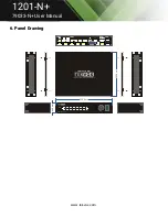
Page 38: ...I 2 HDMI AUTO RES RESET 3s MENU 3s ENTER TEK 1201 HD N 6 input Seamless Scaler Switcher with HDBaseT TEK 1201 HD N DC 24V POWER IN HDBT L R HDMI OUT 1 HDMI MHL IR IN IR OUT IR EYE TCP IP RS232 Tx Rx CONTROL AUDIO OUT 1 AUDIO 2 AUDIO L R MIX AUDIO IN 6 VGA 6 AUDIO 2 HDMI 3 HDMI 4 HDMI 5 HDMI 250 0 mm 200 0 mm 44 0 mm ...

Page 39: ...etermine if there is a signal at the input and output end If there is no signal the connection cord may be broken or have loose connections Use a new cable and or attempt to reconnect them If none of these methods have worked there may be something wrong with the switcher Contact your dealer if this is the case 6 If the static becomes stronger when connecting the video audio connectors the groundi...

Page 40: ...removed from the product Damage deterioration or malfunction caused by Normal wear and tear Use of supplies or parts not meeting our specifications No certificate or invoice as the proof of warranty The product model shown on the warranty card does not match with the model of the product for repairing or had been altered Damage caused by force majeure Servicing not authorized Other causes which do...

Reviews: