


Operating basics
Display, navigation, and menus
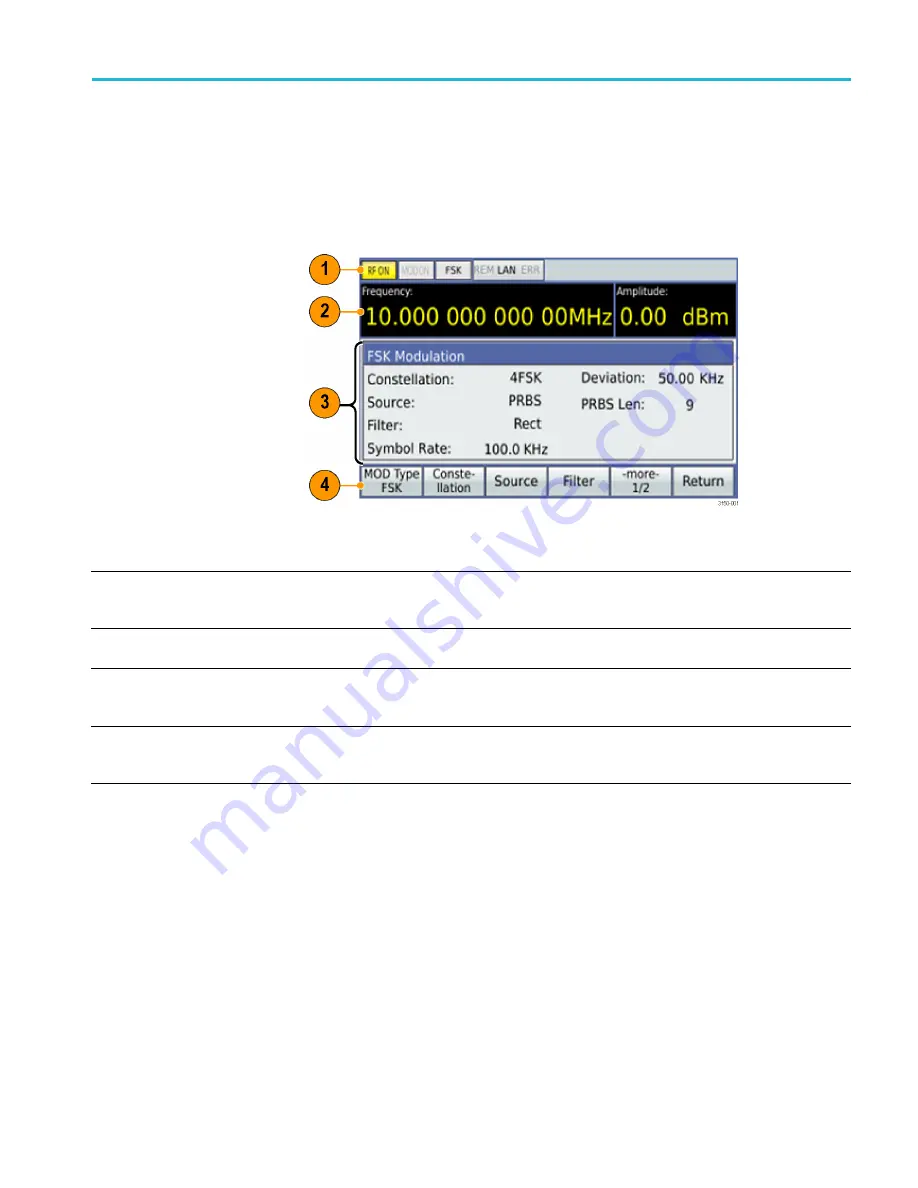
Controls and display elements are shown in the following illustrations and tables.
Display
The display screen is divided into the following four sections:
Ref
number
Display area function
Description
1
Status
Indicates instrument status. When an item is highlighted yellow or is displayed with bold
typeface, that feature is active. This area shows modulation types, and if Modulation and
RF are ON or Off. Error messages, if applicable, show in the right corner of this area.
2
Quick view
Shows frequency and amplitude values. Units can be changed using the unit buttons
on the front panel.
3
Settings
Shows the parameters that can be modi
fi
ed for the currently selected item. You can
modify a parameter by pressing the corresponding menu button and then using the arrow
keys, general knob, and Enter key on the front panel.
4
Menus
Menu buttons show items that you can select to access submenus for speci
fi
c actions,
such as LAN or GPIB setup, or setting a particular modulation type. Use the arrow keys,
general knob, and Enter key on the front panel to navigate the menus.
Saving display images
(screen shots)
You can save *.bmp
fi
les of the instrument display to a USB memory device as
follows:
1.
Insert a USB memory device into the USB port on the front of the instrument.
2.
Set the display as desired.
3.
Simultaneously press and hold the
<
and
>
keys for 1 second.
4.
Remove the memory device and download the saved *.bmp
fi
les to your PC
or other device.
TSG4100A Series RF Signal Generators User Manual
15


