background image

How to install and con

fi

gure Option DPW

b.

Pull out the handle located at the bottom of the supply. (See Figure 2.)

c.

While pushing the retaining latch to the left, use the handle to pull the
Power Supply module out of the instrument.

3.

Insert the replacement supply into the instrument until it latches into place.

4.

If necessary, push the handle of the supply into the storage position.

5.

Connect the power cable to the Power Supply module you installed.

6.

Check that the status of the Power Supply module you just installed is bright
green or dim green.

7.

If desired, change the preferred supply con

fi

guration. (See page 11,

Con

fi

gure

the preferred (active) supply

.)

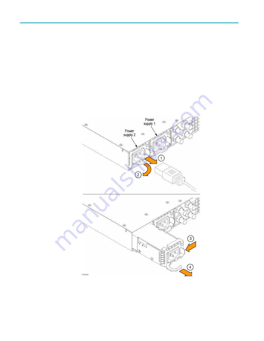
Figure 2: Removing an installed Power Supply module

10

SPG70UP Field Upgrade Instructions

Summary of Contents for SPG700

Page 1: ...SPG700 Multiformat Reference Sync Generator SPG70UP Field Upgrade ZZZ Instructions xx www tek com P075109300 075 1093 00 ...

Page 2: ...sued and pending Information in this publication supersedes that in all previously published material Specifications and price change privileges reserved TEKTRONIX and TEK are registered trademarks of Tektronix Inc Contacting Tektronix Tektronix Inc 14150 SW Karl Braun Drive P O Box 500 Beaverton OR 97077 USA For product information sales service and technical support In North America call 1 800 8...

Page 3: ...uipment 8 How to prevent component damage 8 Install the backup Power Supply module 9 Configure the preferred active supply 11 How to upgrade the instrument firmware 13 Determine if a firmware upgrade is needed 13 Backup user files to a USB drive 15 Firmware upgrade overview 16 USB firmware upgrade 17 Network firmware upgrade 19 Verify the firmware upgrade 22 Restore user files from a USB drive 22 ...

Page 4: ...Table of Contents ii SPG70UP Field Upgrade Instructions ...

Page 5: ...of the product it is essential that you follow generally accepted safety procedures in addition to the safety precautions specified in this manual The product is designed to be used by trained personnel only Only qualified personnel who are aware of the hazards involved should remove the cover for repair maintenance or adjustment Before use always check the product with a known source to be sure i...

Page 6: ...at terminal Do not operate without covers Do not operate this product with covers or panels removed or with the case open Hazardous voltage exposure is possible Avoid exposed circuitry Do not touch exposed connections and components when power is present Do not operate with suspected failures If you suspect that there is damage to this product have it inspected by qualified service personnel Disab...

Page 7: ...roduct Only qualified personnel should perform service procedures Read this Service safety summary and the General safety summary before performing any service procedures To avoid electric shock Do not touch exposed connections Do not service alone Do not perform internal service or adjustments of this product unless another person capable of rendering first aid and resuscitation is present Discon...

Page 8: ...n the product DANGER indicates an injury hazard immediately accessible as you read the marking WARNING indicates an injury hazard not immediately accessible as you read the marking CAUTION indicates a hazard to property including the product When this symbol is marked on the product be sure to consult the manual to find out the nature of the potential hazards and any actions which have to be taken...

Page 9: ...o the SPG700 generator This section also describes how to configure one of the Power Supply module as the preferred active supply See page 8 How to upgrade the instrument firmware describes how to install the latest version of firmware See page 13 Firmware upgrade Tektronix releases software and firmware updates for products to add new features and to fix product problems You can find the latest f...

Page 10: ...ational power cord options All of the available power cord options except as noted below include a lock mechanism to keep the power cord attached to the instrument Opt A0 North America power standard Opt A1 Universal EURO power Opt A2 United Kingdom power Opt A3 Australia power Opt A5 Switzerland power Opt A6 Japan power Opt A10 China power Opt A11 India power no locking cord Opt A12 Brazil power ...

Page 11: ...rovides procedures for verifying the performance of the instrument Service Manual 077 1229 xx Describes how to service the instrument to the module level such as circuit boards and fuses Declassification and Security Instructions 077 1230 xx Describes how to clear or sanitize the data storage memory devices in the product for customers with data security concerns Release Notes 077 1231 xx Describe...

Page 12: ...ts on the modules and mainframe To prevent ESD or other component damage follow the steps below when installing removing or handling modules Wear a grounded antistatic wrist strap to discharge the static voltage from your body while installing or removing modules from the mainframe Transport and store modules in a static protected bag or container Do not slide the module over any surface Handle mo...

Page 13: ...that you are replacing WARNING Disconnect the power cord from a Power Supply module before you remove the module from the instrument Also do not connect a power cord to a Power Supply module while the module is not installed in the instrument There are dangerous high voltages on the module when the power cord is connected CAUTION To prevent an unexpected shutdown of the instrument be sure to unplu...

Page 14: ... instrument until it latches into place 4 If necessary push the handle of the supply into the storage position 5 Connect the power cable to the Power Supply module you installed 6 Check that the status of the Power Supply module you just installed is bright green or dim green 7 If desired change the preferred supply configuration See page 11 Configure the preferred active supply Figure 2 Removing ...

Page 15: ...t of the preset system Therefore the preferred supply configuration will not change when you activate any of the system presets including the Factory Default preset Perform the following steps to configure which Power Supply module is the preferred active supply 1 Check the status of the front panel PWR1 and PWR2 indicators Bright green indicates the preferred active supply Dim green indicates the...

Page 16: ...ontinue this procedure Otherwise you do not need to change the preferred supply configuration 4 If you want to change the preferred supply configuration press the SYSTEM button to access the SYSTEM menu 5 Press the up or down arrow button to select SYSTEM POWER SUPPLY PREFERRED SELECT 6 Press the left or right arrow button to display the supply you want to be the primary active supply Power Supply...

Page 17: ... firmware on your instrument should be upgraded and to backup your user files CAUTION The firmware upgrade process replaces all installed user files with the factory default files To prevent the loss of your user files including custom test signals logo and ID text overlays and saved presets be sure to backup all of your user data before you perform the upgrade The following procedure includes ins...

Page 18: ...s into the directory of your choice transfer exe and firmware pkg NOTE If a readme txt file is included in the firmware package be sure to read the file before you upgrade the firmware 7 If the firmware in your instrument needs to be upgraded verify which options are currently installed before you install the software After you install the upgrade you will verify that any previously installed opti...

Page 19: ... using a different USB device from a well known brand that is 16 GB or less 3 Use the up or down arrow button to select SYSTEM BACKUP RESTORE 4 Use the left or right arrow button to select Backup All User Data to USB and then press the ENTER button CAUTION To prevent the loss of your user files be sure to use the Backup All User Data to USB option in the backup procedure 5 In the overwrite confirm...

Page 20: ...nstrument flash may be corrupted and you will have to run the recovery procedure See page 23 Troubleshoot the firmware upgrade NOTE If power to the instrument is lost before it begins erasing the internal flash you can restart the firmware upgrade after the instrument reboots If the instrument displays only a blank screen after power is reapplied see the troubleshooting section for help See page 2...

Page 21: ...have a directory path of SpgUpgrd firmware pkg 5 Eject and safely remove the USB device from the computer 6 If necessary power on the instrument and wait for the instrument to fully boot up before inserting the USB device into the front panel USB port on the instrument 7 Press the SYSTEM button to access the SYSTEM menu 8 Verify that the USB device is properly installed by pressing the up or down ...

Page 22: ...r files before performing the upgrade The instructions for backing up user files is described in the section To transfer user files from an instrument to a USB drive See page 15 You will restore the user files at the end of the upgrade procedure 12 Press the ENTER button to proceed with the upgrade or press the BACK button to cancel the upgrade 13 When you press ENTER the upgrade process begins Du...

Page 23: ...rs 16 Proceed to Verify the firmware upgrade See page 22 Network firmware upgrade Use the following steps to upgrade the instrument firmware using a network connection 1 Connect the instrument and a Windows PC to your local Ethernet network or directly connect the instrument to a Windows PC 2 Power on the instrument 3 Prepare the instrument for the firmware upgrade a Press the SYSTEM front panel b...

Page 24: ...s from an instrument to a USB drive See page 15 You will restore the user files at the end of the upgrade procedure e Press the ENTER button to proceed with the upgrade or press the BACK button to cancel the upgrade f When you press ENTER a Waiting for network connection message is displayed along with the IP address of the instrument This indicates the instrument is ready to be upgraded An exampl...

Page 25: ...u will have to run the recovery procedure See page 23 Troubleshoot the firmware upgrade NOTE The upgrade will not proceed until all of the firmware data is transferred to the instrument Once the upgrade has started the instrument will attempt to complete the upgrade even if it loses contact with transfer exe So that you can monitor the progress of the upgrade it is suggested that you do not close ...

Page 26: ...version is the same version as the firmware package you used to perform the upgrade 7 If you backed up your user files to a USB drive before you upgraded the firmware proceed to Restore user files from a USB drive Restore user files from a USB drive If you backed up your user files to a USB drive before you upgraded the firmware perform the following steps to restore the user files 1 Insert a USB ...

Page 27: ...select SYSTEM USB Mounted 8 Press the ENTER button to safely unmount the USB device Troubleshoot the firmware upgrade If a power failure occurs during the upgrade and the instrument has a blank screen when you reapply power perform the following procedure 1 Connect an Ethernet cable between the instrument and your computer or local Ethernet network 2 Remove the power cable to turn off the instrume...

Page 28: ...mputer and you want to use the previously saved static IP address assigned to the instrument for the upgrade The saved IP address is displayed Quit and continue booting Use this selection to quit the upgrade process and leave the instrument in its current condition 6 If you did not select Quit and continue booting in the previous step the top line of the instrument display will show the message Wa...

Reviews: