Tektronix DC 509, Instruction Manual
Looking for the Tektronix DC 509 Instruction Manual? Look no further! You can download the manual for free from manualshive.com. The manual provides detailed instructions on how to operate the Tektronix DC 509, ensuring you get the most out of this high-quality product.
Share
Download


Reviews:
No comments
Related manuals for DC 509
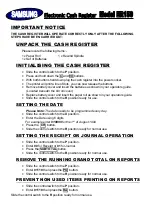
ER-150
Brand: Samsung Pages: 2

ECR 7900
Brand: Olivetti Pages: 62

HopperOne S11
Brand: Alberici Pages: 12

DT200
Brand: Deteck Pages: 28

EV-020
Brand: MZ electronic Pages: 124

1700w
Brand: Hantle Pages: 101

CNT-700
Brand: Samwon ENG Pages: 21
XE-A203 - Cash Register Thermal Printing Graphic Logo Creation
Brand: Sharp Pages: 31

XE-A207
Brand: Sharp Pages: 153

XE-A212
Brand: Sharp Pages: 404

XE-A207
Brand: Sharp Pages: 25

XE-A203A
Brand: Sharp Pages: 151

XE-A212
Brand: Sharp Pages: 28

XE-A206
Brand: Sharp Pages: 2
XE-A203 - Cash Register Thermal Printing Graphic Logo Creation
Brand: Sharp Pages: 454

XE-A202 - Electronic Cash Register
Brand: Sharp Pages: 27

XE-A207W
Brand: Sharp Pages: 2

JetCount 4020
Brand: CUMMINS ALLISON Pages: 45


