background image

Instrument interface, front panel, and rear panel

Instrument interface, front panel, and rear panel

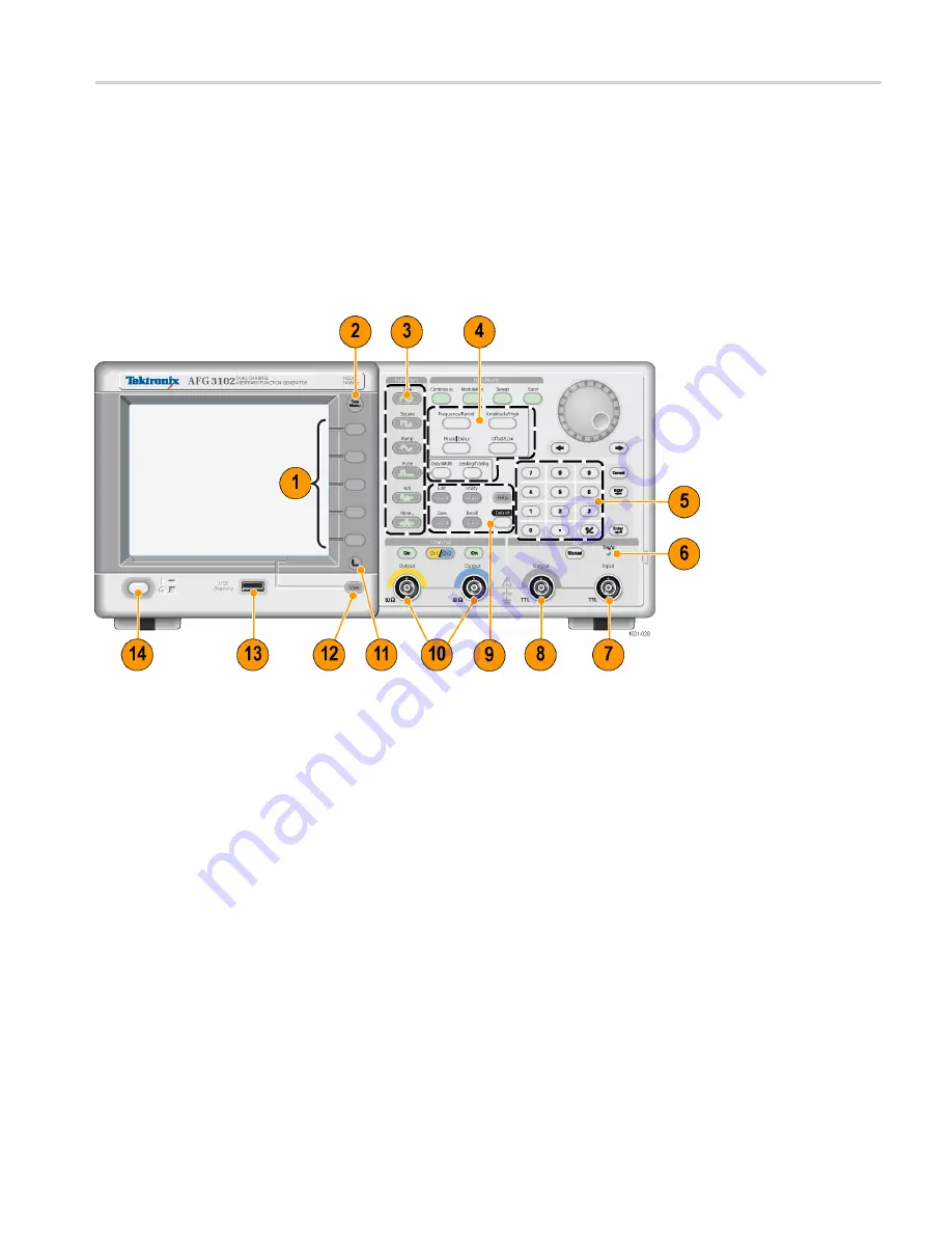
Front panel overview

The front panel is divided into easy-to-use functional areas. This section provides
you with a quick overview of the front panel controls and the screen interface.
The following

fi

gure shows the front panel of the dual-channel model.

1.

Bezel menu buttons

2.

Top menu button

3.

Function buttons

4.

Shortcut buttons

5.

Numeric keypad

6.

Triggered LED is lit when the instrument receives an internal or external
trigger

7.

Trigger input connector

8.

Trigger output connector

9.

Menu buttons

10.

CH 1 and CH 2 output connectors

11.

Return to previous menu button

12.

View button

AFG3000 and AFG3000C Series User Manual

25

Summary of Contents for AFG3000 Series

Page 1: ...xx AFG3000 and AFG3000C Series Arbitrary Function Generators ZZZ User Manual P077095701 077 0957 01 Test Equipment Depot 800 517 8431 99 Washington Street Melrose MA 02176 TestEquipmentDepot com...

Page 2: ......

Page 3: ...AFG3000 and AFG3000C Series Arbitrary Function Generators ZZZ User Manual xx...

Page 4: ...aws and international treaty provisions Tektronix products are covered by U S and foreign patents issued and pending Information in this publication supersedes that in all previously published materia...

Page 5: ...tomer shall be responsible for paying all shipping charges duties taxes and any other charges for products returned to any other locations This warranty shall not apply to any defect failure or damage...

Page 6: ......

Page 7: ...from misuse 12 Floating ground 14 Protect your DUT 15 Update your instrument firmware 16 Connect to a network 18 Equivalent Output Circuits 22 Overheat Protection AFG3011 3011C Only 24 Instrument inte...

Page 8: ...up Load Impedance 68 Invert Waveform Polarity 69 Add Noise 70 Add Signal AFG3100 and AFG3200 Series 71 Generating a Differential Signal 72 External Reference Clock 74 Synchronous Operation 75 USB Memo...

Page 9: ...List of Figures Figure 1 Fuse and fuse adapter 13 AFG3000 and AFG3000C Series User Manual iii...

Page 10: ...Table 1 General features for regular and B models 1 Table 2 General features for AFG30xxC models 2 Table 3 General features for AFG31xxC and AFG32xxC models 3 Table 4 Standard accessories 5 Table 5 Op...

Page 11: ...ironment and to reduce the use of natural resources we encourage you to recycle this product in an appropriate system that will ensure that most of the materials are reused or recycled appropriately T...

Page 12: ...Environmental Considerations vi AFG3000 and AFG3000C Series User Manual...

Page 13: ...102C AFG3151C AFG3152C AFG3251C AFG3252C Where to find more information The following table lists related documentation available for your instrument The documentation is available on the Document CD...

Page 14: ...pliance Instructions that were shipped with your instrument for general safety summary EMC compliance and safety compliance information Conventions Used in this Manual The following icons are used thr...

Page 15: ...ature AFG3011 AFG3021B AFG3022B AFG3101 AFG3102 AFG3251 AFG3252 Channel 1 1 2 1 2 1 2 Sine 10 MHz 25 MHz 100 MHz 240 MHz Pulse 5 MHz 12 5 MHz 50 MHz 120 MHz Memory 2 to 131 072 2 to 131 072 2 to 16 38...

Page 16: ...MHz Memory 2 to 131 072 2 to 131 072 2 to 131 072 16 384 to 131 072 Sampling Rate 250 MS s 250 MS s 1 GS s 250 MS s Amplitude 20 Vp p 10 Vp p 10 Vp p Display Color Color Color Interface USB LAN GPIB U...

Page 17: ...ry 2 to 16 384 16 384 to 131 072 2 to 16 384 16 384 to 131 072 2 to 16 384 16 384 to 131 072 Sampling Rate 1 GS s 1 GS s 1 GS s 250 MS s 2 GS s 250 MS s Amplitude 10 Vp p 10 Vp p 5 Vp p Display Color...

Page 18: ...s Sides 50 mm 2 in Rear 50 mm 2 in 2 Before operating ensure that the ambient temperature is between 0 C to 50 C 32 F to 122 F CAUTION To ensure proper cooling keep both sides of the instrument clear...

Page 19: ...xx Portuguese 1 077 0963 xx Simplified Chinese 1 077 0964 xx Traditional Chinese 1 077 0965 xx Korean 1 077 0966 xx Spanish AFG3000 Series Arbitrary Function Generators Programmer Manual 077 0743 xx...

Page 20: ...cifications connect only high quality shielded cables to this instrument High quality shielded cables typically are braid and foil types that have low impedance connection to shielded connectors at bo...

Page 21: ...e AC power cord into the power receptacle on the rear panel 2 Push the front panel power button to power on the instrument Wait until the front panel display shows that the instrument has passed all p...

Page 22: ...ou can restore the instrument to its default settings at any time by pushing the front panel Default button 1 Push the front panel Utility button 2 Push the System bezel button 3 Push the Power On bez...

Page 23: ...ncel bezel button to cancel the operation Perform instrument self test and self calibration The instrument performs a limited set of hardware tests at power on You can also perform the following manua...

Page 24: ...xecuting self calibration If the power is turned off during self calibration data stored in the internal memory may be lost Quick Tips Before executing self calibration ensure that the ambient tempera...

Page 25: ...h German Japanese Korean Simple Chinese Traditional Chinese and Russian Quick Tips When you power on the instrument for the first time English is selected by default After you select a desired languag...

Page 26: ...from the output connectors to avoid making the wrong connection The instrument input and output connectors are floating inputs outputs WARNING To avoid personal injury due to electric shock do not app...

Page 27: ...ect the output circuits a fuse adapter is provided as an optional accessory When the instrument is used by students or other inexperienced users always attach the fuse adapter to the output connectors...

Page 28: ...in use CAUTION The maximum rated voltage between the chassis ground and common ground is 42 Vp p DC peak AC When the potential voltage between the chassis ground and common ground goes over 42 Vp p th...

Page 29: ...Menu 2 In this example High Limit is set to 5 000 V and Low Limit is set to 5 000 V 3 Push the Limit bezel button 4 Select High Limit Use numeric keys or the general purpose knob to enter a value Ente...

Page 30: ...example The actual screen display may be different depending on your instrument configuration 1 Push the front panel Utility button to display the Utility menu Version information is displayed on the...

Page 31: ...ct the downloaded firmware file by rotating the general purpose knob and then push the Execute bezel button 7 Follow the on screen instructions 8 Check that the clock symbol at the top right of the sc...

Page 32: ...sing the Security menu Connect to a network The AFG3000 series arbitrary function generator communication interface allows you to communicate with or remotely control your instrument You can use a USB...

Page 33: ...Push the front panel Utility button 3 Push the I O Interface Ethernet bezel buttons 4 The Ethernet Network Settings menu is displayed By selecting the DHCP On the instrument can set its network addre...

Page 34: ...act your network administrator to get the IP address to use 7 Push the Subnet Mask bezel button to enter a Subnet Mask Ask your network administrator whether a subnet mask is required 8 Push the Defau...

Page 35: ...evice connected to the GPIB bus must have a unique GPIB address The GPIB address must be from 0 to 30 5 Push the Configuration bezel button to toggle the instrument bus communications on and off Talk...

Page 36: ...ut Circuits The following illustrations show the equivalent output circuits for the AFG3000 series instruments 1 AFG3011 3011C Output signals do not exceed 20 V when the 50 load impedance is used 2 AF...

Page 37: ...used Voltage over the maximum level is clipped Amplitude and offset are affected when you change the load impedance The maximum and minimum levels do not exceed 10 V respectively 4 AFG3251 3251C 3252...

Page 38: ...vel Minimum level Maximum amplitude 10 V 10 V 10 Vp p 10 V 10 V 20 Vp p AFG3251 3251C 3252 3252C Maximum level Minimum level Maximum amplitude 5 V 5 V 5 Vp p 10 V 10 V 10 Vp p Overheat Protection AFG3...

Page 39: ...e screen interface The following figure shows the front panel of the dual channel model 1 Bezel menu buttons 2 Top menu button 3 Function buttons 4 Shortcut buttons 5 Numeric keypad 6 Triggered LED is...

Page 40: ...labeled bezel buttons directly to the right of the screen Some documentation may also refer to the bezel buttons as option buttons side menu buttons or soft keys Main display area and View tab Pushing...

Page 41: ...mplitude level of your instrument 2 Shows the range of high limit and low limit set by the user 3 Shows the amplitude level that is currently selected View button The instrument provides the following...

Page 42: ...utton once the view format is changed to the graph comparison format Push the View button again to display the third format This view provides the channel parameter comparison Quick Tips If the instru...

Page 43: ...pulse waveform 2 If you push the Amplitude High shortcut button once Amplitude becomes active 3 If you push the Amplitude High shortcut button again High Level becomes active You can also set paramete...

Page 44: ...nstrument displays a 1 MHz frequency 1 Vp p amplitude sine waveform as the default setup Quick Tips The AFG3000 Series Arbitrary Function Generators Programmer Manual describes the default setup setti...

Page 45: ...aussian Lorentz Exponential Rise Exponential Decay and Haversine The instrument can also provide user defined arbitrary waveforms You can create edit and save your custom waveforms You can also create...

Page 46: ...Decay Haversine Pulse Noise DC Continuous Modulation AM FM PM FSK PWM Sweep Burst NOTE When the instrument outputs an Arb waveform Vp p of instrument setup indicates the Vp p value of normalized wavef...

Page 47: ...directly select one of four standard waveforms from the front panel Function buttons 3 To select an arbitrary waveform push the Arb button 4 To select other standard waveforms such as Sin x x Noise D...

Page 48: ...t interface front panel and rear panel 7 These are waveform examples of Lorentz and Haversine 8 These are waveform examples of Exponential Rise and Exponential Decay 34 AFG3000 and AFG3000C Series Use...

Page 49: ...instrument signal output method 1 The default Run Mode is Continuous You can read more about changing waveform parameters See page 36 2 To select a modulated waveform push the Modulation button You c...

Page 50: ...ee page 54 Adjust Waveform Parameters When you turn on your instrument the default output signal is a 1 MHz sine waveform with an amplitude of 1 Vp p In the following example you can change the freque...

Page 51: ...cut button 6 Amplitude is now active You can change the value using the keypad and Units bezel menu or you can change the value using the general purpose knob 7 Push the Amplitude High shortcut button...

Page 52: ...99 dBm 632 mVp p 224 mVrms 0 00 dBm 283 mVp p 100 mVrms 6 99 dBm 200 mVp p 70 7 mVrms 10 00 dBm 10 0 mVp p 3 54 mVrms 36 02 dBm Channel Select dual channel model only 1 Push the front panel Channel S...

Page 53: ...On state You can configure the signal with the outputs off This will allow you to minimize the chance of sending a problematic signal to a DUT 2 Dual channel model only You can turn on or off the sig...

Page 54: ...trary function generator and another instrument use the external reference input connector 4 EXT REF OUTPUT This is a BNC connector for the external reference output When you want to synchronize multi...

Page 55: ...select a waveform parameter 7 Select Frequency as a parameter to be changed 8 Change the frequency value using the numeric keys 9 Change the waveform parameters using the general purpose knob and the...

Page 56: ...he screen If the instrument outputs a default sine waveform you can manually set the oscilloscope as follows 0 5 s div 200 mV div 6 To change the frequency push the front panel Frequency Period shortc...

Page 57: ...y value using the general purpose knob and the arrow keys To increase the value turn the knob clockwise To change a specific digit select it by pushing the arrow keys Then change it by turning the kno...

Page 58: ...ding to the highlighted link 4 Push the Index bezel button to display an Index page 5 Push the Exit bezel button or any front panel button to remove the Help text from the screen and return to the gra...

Page 59: ...toggle the parameters for Leading Edge and Trailing Edge 5 You can set the lead delay by pushing the Phase Delay shortcut button to display the lead delay setting screen and adjusting the parameter a...

Page 60: ...emp1 0 8 2 0 width tEdge Temp2 period leadDelay width 0 8 2 0 tEdge Temp3 0 625 period Maximum trailing edge time This value is the minimum of the three in each instance If runMode Continuous Temp1 0...

Page 61: ...t panel Edit button to display the Edit menu 2 Select Read from to recall an arbitrary waveform 3 The Read Waveform page is displayed 4 To save waveforms select Write to to display the Write Waveform...

Page 62: ...e internal memory or USB memory Select Internal You can specify a file from the following User 1 User 2 User 3 or User 4 Edit Memory 1 or Edit Memory 2 NOTE Edit Memory 2 is only available on dual cha...

Page 63: ...etween these two memories 1 Push the front panel Edit button to display the Edit Menu 2 Select Number of Points to set the number of waveform points to be edited 3 Select New to write a standard wavef...

Page 64: ...ct Paste at Beginning to append a waveform at the beginning of the edit waveform Select Paste at End to append a waveform at the end of the edit waveform 8 Select Copy to EMEM1 EMEM2 to copy waveform...

Page 65: ...Next create a 500 point ramp waveform 4 Select Operation and select Line Do the following line edit X1 1 Y1 8191 X2 250 Y2 16382 Push Execute Once again select Line from Operation and perform the fol...

Page 66: ...r1 2 Push the front panel View button to change the screen to Table display 3 Push Operation and select Data 4 Perform the following data point edit X 250 Y 8191 X 251 Y 8191 X 750 Y 8191 X 751 Y 8191...

Page 67: ...w button in the Edit Menu to toggle between edit texts and graphical views Push the front panel Channel Select button to toggle between the Edit Memory 1 and Edit Memory 2 menus Generate Noise DC 1 Pu...

Page 68: ...ed Burst Mode The instrument outputs a continuous waveform when an effective gate signal is applied externally when the Manual Trigger button is depressed when a remote command is applied or during 50...

Page 69: ...burst menu 2 Select Gate 3 This is a sample oscilloscope screen The top waveform is a trigger output signal 4 This is a gated waveform sample Quick Tips The instrument provides the following three tri...

Page 70: ...he front panel Sweep button 2 You can specify the start frequency stop frequency sweep time and return time from the sweep menu Return Time represents the amount of time from Stop Frequency to Start F...

Page 71: ...eat or Trigger and trigger source 5 This is a sample oscilloscope screen The top is a sample of a sweep waveform 6 This is a trigger output signal Quick Tips For frequency sweep you can select a sine...

Page 72: ...ting other menus push the front panel Sweep button again Modulate a Waveform To Output an AM Waveform 1 Select a waveform and then push the front panel Modulation button In this example use sine wavef...

Page 73: ...lect an internal or external signal as an AM source If you select an external source and set the modulation depth to 120 the output will be at the maximum amplitude when a 1 Vp p signal is applied to...

Page 74: ...h M FM Deviation D Hz PM Deviation P degree The following table shows relationship between modulation depth and maximum amplitude for AM modulation waveform internal modulation source is selected Dept...

Page 75: ...modulation type selection submenu See page 58 Modulate a Waveform In this example select FSK as the modulation type 2 The FSK parameter setting screen is displayed Select Internal or External as FSK...

Page 76: ...the front panel Pulse button and then push the Pulse Parameter Menu bezel button to display the pulse parameter setting screen 2 Push the front panel Modulation button to display the PWM parameter set...

Page 77: ...igger input connector of the oscilloscopes The Trigger Output connector provides the trigger signal for oscilloscopes 2 Continuous mode The trigger output is a square waveform and the rising edge at t...

Page 78: ...external modulation source is selected the trigger output is disabled 5 Burst Mode When internal trigger source is selected the trigger output is a square waveform and the rising edge at the start of...

Page 79: ...tputs a modulation waveform Trigger Output signal cannot be output if you select External as the modulation source Adjusting Parameters of Two Channel Signals dual channel models only Phase The AFG300...

Page 80: ...ck to 5 MHz In this state the CH2 phase does not return to its initial condition 3 To align the phase of two channel signals push the Align Phase bezel button 4 When you push the Align Phase button th...

Page 81: ...he CH1 and CH2 amplitude to the same level by selecting On in the second bezel menu from the top Frequency Period To set the CH1 frequency and CH2 frequency to the same value follow these steps 1 Push...

Page 82: ...the Output Menu bezel button The Output Menu is displayed 2 Push Load Impedance to display the Load Impedance submenu 3 To adjust the load impedance select Load 4 You can set the load impedance to an...

Page 83: ...equency Period button 3 Push the Frequency bezel button to set the CH1 frequency 4 Select the third bezel button from the top to set the two channel frequencies to the same value 5 Push the front pane...

Page 84: ...tput Menu See page 68 To add noise to a sine waveform push Noise 3 The Noise Add submenu is displayed Push Noise Add to select On 4 To adjust the noise level push Noise Level Use the general purpose k...

Page 85: ...to On the amplitude of output signal is reduced to 50 Add Signal AFG3100 and AFG3200 Series The AFG3101 3101C 3102 3102C 3151C 3152C and AFG3251 3251C 3252 3252C rear panel ADD INPUT connector allows...

Page 86: ...dding external signal noise Quick Tip The Output Status is changed from Output Off to Ext Add when you push the front panel CH1 Output button to enable the output Generating a Differential Signal A du...

Page 87: ...push the Output Menu bezel button 3 Push the CH1 Complement bezel button 4 The CH2 wave shape and timing parameters are copied from CH1 and the CH2 amplitude settings are inverted from CH1 NOTE When...

Page 88: ...ut and Output connectors are used for synchronizing multiple AFG3000 series instruments The instrument can use the internal source or an external source as a reference signal When the internal referen...

Page 89: ...another unit slave The master unit sends a trigger signal to the slave unit 2 Connect the rear panel EXT REF OUT master and EXT REF IN slave with another BNC cable The master clock and the slave clock...

Page 90: ...ernal Confirm that Internal is selected in the master and External is selected in the slave for Source 9 This screen shows signal outputs by master slave operation The top waveform is the signal of th...

Page 91: ...the screen Do not remove the USB memory until the message disappears If you remove the USB memory while this caution message is displayed it may cause damage to the instrument Read more about saving...

Page 92: ...Push the Status bezel button to display the instrument status Push the System bezel button to display the System submenu 6 Trigger Out See page 63 7 Reference Clock See page 74 8 You can select the i...

Page 93: ...up Restore bezel button to display the Backup Restore submenu In this menu you can back up a waveform data from internal memory to USB memory or restore a waveform data from USB memory to internal mem...

Page 94: ...a file name in this screen Use the general purpose knob to select a character Push the Enter Character bezel button or the front panel Enter key to enter the character 5 To recall a setup push the fro...

Page 95: ...screen indicating that the screen image was saved 4 Push OK Quick Tips Image files are saved in a folder named TEK in the USB memory Image files are saved as BMP format The instrument gives all files...

Page 96: ...e characters and push the Enter Character bezel button after each selection As you enter the characters of your password they are displayed as a series of asterisks on the password input page If no sp...

Page 97: ...of your new password they are displayed on the screen Check carefully to ensure you are entering the desired characters 6 Select OK to activate the new password NOTE A password must have at least fou...

Page 98: ...1 Redistributable 800 x 600 Display resolution TekVISA Version 3 3 4 6 and above Create waveforms from standard waveform templates Modify and transfer waveforms to perform DUT level tests Directly im...

Page 99: ...tcut view occupies the left part of the display Use the Shortcut view to quickly access various functions provided by the application Refer to the ArbExpress online help for more information 4 Status...

Page 100: ...ate any of the standard waveforms that are available Use Settings to select a desired waveform and instrument type 4 Use Vertical to set the waveform vertical parameters 5 Use Horizontal to set the wa...

Page 101: ...d in the Resultant Waveform pane This is an example of adding noise to a square waveform 13 You can remotely control Tektronix AWG AFG instruments using ArbExpress From the Communication menu select A...

Page 102: ...eform data that is compatible with the instrument 1 Create a CSV file to use with ArbExpress 2 Enter point or time to this column 3 Enter data to this column When you open a CSV file a dialog box may...

Page 103: ...to a USB memory and load the waveform in the arbitrary function generator 6 The AFG3000 series instruments output recalled waveform data This is an example of the oscilloscope screen 1 Fs represents s...

Page 104: ...Operating basics 90 AFG3000 and AFG3000C Series User Manual...

Page 105: ...xamples highlight the features of the instrument and give you ideas for using it to solve your own test problems Lissajous Patterns Use your AFG3000 series dual channel model to create a Lissajous pat...

Page 106: ...e Continuos Amplitude 1 V CH1 Frequency 400 kHz CH2 Frequency 500 kHz 2 Set the oscilloscope display format to XY Adjust the amplitude so that the waveform is shown in the graticule A Lissajous patter...

Page 107: ...nnect the Trigger Output of the instrument and the external trigger input connector of an oscilloscope Set the oscilloscope input impedance to 50 3 Select Sweep from Run Mode of the instrument and set...

Page 108: ...nstrument output and a DUT using a BNC to alligator clip adapter 2 Select Pulse as an output waveform and then select PWM as a modulation type Set the frequency to approximately 100 kHz 3 Connect the...

Page 109: ...ine as an output waveform and then select FM as the modulation type 2 Set the waveform parameters as follows Carrier frequency 1 MHz Modulation frequency 2 kHz 3 Change Deviation Set the deviation to...

Page 110: ...Application Examples 96 AFG3000 and AFG3000C Series User Manual...

Page 111: ...t to a network 18 CSV file ArbExpress 88 D DC Standard waveform 33 Default button 8 Default setup 30 Default Power on settings 8 Differential signal 69 72 Double pulse 54 E Edit menu 49 Recalling wave...

Page 112: ...Noise 70 Output On Off 39 Output status Noise 71 screen interface 26 Output window 24 Overheat protection 24 P Parameters how to adjust 36 Period Phase 65 Phase Delay shortcut button 29 Power button 7...

Page 113: ...nal 71 To invert waveform 55 To protect your DUT 15 To output a PWM waveform 62 To output an FSK waveform 61 To protect your DUT To set up load impedance 68 To select a local language 11 Top menu butt...

Reviews: