background image

SECTION


TWO

OPERATING


INSTRUCTIONS

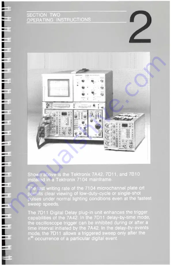
Shown


above is 

the


Tektronix


7A42,


7D1

1, and


7B10


installed


in

 a

 Tektronix


7104


mainframe.

The


fast


writing


rate

 of


the


7104


microchannel


plate 

crt


permits clear

 viewing


of

 low-duty-cycle 

or


single-shot


pulses


under


normal lighting

 conditions

 even


at


the


fastest 

sweep

 speeds.

The 

7D11 

Digital 

Delay

 plug-in 

unit 

enhances


the


trigger


capabilities

 of 

the

 7A42.


In

 the 7D11 

delay-by-time

 mode, 

the


oscilloscope


trigger

 can

 be 

inhibited

 during


or


after


a


time 

interval


initiated


by


the

 7A42. 

In


the

 delay-by-events 

mode,


the


7D1

1


allows


a


triggered


sweep

 only


after


the 

n

th

 occurrence of a


particular 

digital


event.

Summary of Contents for 7A42

Page 1: ...2 070 4285 00 OPERATORS MANUAL Logic Triggered Vertical Amplifier Please check for change information at the rear of this manual First Printing APRIL 1983 Revised JUL 1984 Tektronix COMMITTED TO EXCEL...

Page 2: ...PROBES 1 24 2 OPERATING INSTRUCTIONS OPERATION 2 1 SIMPLIFIED BLOCK DIAGRAM OF 7A42 2 1 BOOLEAN ALGEBRA FOR 7A42 USE 2 3 CONTROLS CONNECTORS AND INDICATORS 2 9 GET ACQUAINTED EXERCISES 2 13 EXERCISE...

Page 3: ...PUT 2 62 RESET INPUT 2 62 TRIGGER OUT 2 62 PROG CHAN TRIG 2 64 PROGRAM CHANNEL MODE 2 64 CH1 CH2 CH3 CH4 2 65 DISPLAY 2 65 TTL ECL 2 65 VOLTS DIV 2 65 GND 2 65 1M 50 2 65 THRESH 2 65 PROBE OFFSET 2 66...

Page 4: ...ING 3 11 COUNTING CLOCK CYCLES BETWEEN EVENTS 3 12 MEASURING TIME FROM FUNCTION A TO FUNCTION B 3 12 APPLICATION 6 OFFSET PROBING TECHNIQUES FOR HIGH SPEED LOGIC SYSTEMS 3 14 PROBING ECL CIRCUITS 3 15...

Page 5: ...ts of CH1 CH2 CH3 and CH4 2 58 2 15 Timing diagram showing the relationship of the TRIGGER OUT waveform to the input signals 2 63 2 16 Timing diagram depicting the TRIGGER OUT waveform as a result of...

Page 6: ...2 Electrical Characteristics 1 6 1 3 Environmental Characteristics 1 21 1 4 Physical Characteristics 1 22 2 1 7A42 Self Test Failure Messages 2 51 2 2 7A42 Front Panel Control Settings When Initialize...

Page 7: ...RNING statements identify conditions or practices that could result in personal injury or loss of life AS MARKED ON EQUIPMENT CAUTION indicates a personal injury hazard not immediately accessible as o...

Page 8: ...properly wired receptacle before connecting to the product input or output terminals A protective ground connection by way of the grounding conductor in the mainframe power cord is essential for safe...

Page 9: ...ifically designed to display and make measurements on digital logic signals in the TTL ECL and CMOS logic families While the display output from the 7A42 is analog the trigger output is digital and is...

Page 10: ...INFORMATION Shown above is the Tektronix 7A42 7A13 and 7B92A installed in a Tektronix 7904A Oscilloscope The 7904A is a general purpose real time 7000 series mainframe featuring a 300 MHz system band...

Page 11: ...ATORS MANUAL 1 1 SERVICE MANUAL 1 1 INSTALLATION 1 2 INITIAL INSPECTION 1 2 OPERATING TEMPERATURE 1 3 INSTALLING THE 7A42 IN THE MAINFRAME 1 3 MAINFRAME COMPATIBILITY 1 4 PACKAGING FOR SHIPMENT 1 5 SP...

Page 12: ...nt descriptions of the Operators and Service manuals instrument description mainframe and plug in compatibility packaging instructions and instrument specifications Section 2 OPERATING INSTRUCTIONS co...

Page 13: ...s related to the electrical functions of the instrument Section 7 DIAGRAMS AND CIRCUIT BOARD ILLUSTRATIONS includes detailed circuit schematics locations of assembled boards within the instrument volt...

Page 14: ...rtments of a Tektronix 7000 series oscilloscope mainframe NOTE Switch off the mainframe power before installing or removing the 7A42 To install the 7A42 in the mainframe align the grooves in the top a...

Page 15: ...n a single beam configuration Since the 7A42 uses the mainframe CRT readout to display the channel volts per division and error warning messages the 7A42 is not recommended for use in mainframes witho...

Page 16: ...f the original package is unfit for use or not available package the instrument as follows 1 Obtain a corrugated cardboard shipping carton having inside dimensions at least six inches greater than the...

Page 17: ...trument must be operated in a calibrated 7000 series mainframe Any applicable conditions not listed above may be stated as part of the characteristic Environmental characteristics are listed in Table...

Page 18: ...ali brated operation with any calibrated 7000 series mainframe Adjustable at least 4 to 4 from calibrated setting Frequency Response Bandwidth 350 MHz in 7104 0 35 C mainframe am bient temperature Ref...

Page 19: ...ernal protection opens all inputs if overvoltage is applied to any channel 50 Ohm Input Protec tion Reaction Time Maximum time to open input with applied overvoltage of 10 V DC 10 seconds 15 V DC 1 se...

Page 20: ...VOLTS DIV is changed in either TTL or ECL Families or between Families POSITION Range At least 7 divisions to 7 divisions but less than 9 divisions to 9 divisions from graticule center with gain calib...

Page 21: ...aximum Plug in Delay Time Typically 25 ns from channel input to A11 and B11 of mainframe interface connector Channel to Channel Crosstalk Typically less than 0 05 divisions with logic signal inputs ap...

Page 22: ...ns or less Time Coincidence with Channel Display TRIG VIEW Within 3 ns External Clock View Within 5 ns Readout Displayed on crt see detailed operating information TRIGGER SWITCHING THRESHOLD Voltage...

Page 23: ...ut compensation TTL CMOS Family 100 mV ECL Family 20 mV Accuracy at Center Value of Hysteresis Window At Input BNC TTL CMOS Family 5 mV 2 of setting ECL Family 1 mV 2 of setting At tip of 10X probe wi...

Page 24: ...eshold cont At tip of 10X probe with readout compensation TTL CMOS Family 400 mV 20 50 ECL Family 80 mV 20 50 Presets At tip of 10X probe with readout compensation TTL CMOS Family 1 4 V ECL Family 1 3...

Page 25: ...OCK is turned on nor will it operate with any trigger function that contains an edge sensitive channel Match Function A to Function B Within 20 at maximum setting EXT CLOCK Input Maximum Voltage Range...

Page 26: ...atible with a 10X probe TTL Level Approximately 10K ohm in parallel with approximately 55 pF terminated to 5 V ECL Level Approximately 50 ohms terminated to 2 V Minimum Input Slew Rate TTL Level None...

Page 27: ...true before EDGE sensitive channel transition Hold Time Channel to Channel 5 ns minimum Time that level sensitive portion of trigger function must remain true after EDGE sensitive channel transition...

Page 28: ...time 90 to 40 2 ns 1ns A TRIGGER OUT Connector Output Voltage Logic Zero 0 2 V into 50 ohm load Logic One 0 8 V into 50 ohm load Output Impedance Approximately 50 ohms Toggle Frequency 125 MHz maximum...

Page 29: ...event B Time From B to A 5 ns minimum Minimum time after event B to next event A to insure proper arming Event Duration Minimum time to insure proper arming and triggering Event A 5 ns minimum Event...

Page 30: ...ut Active only in A THEN B Mode Amplitude 1 MHz Square Wave 300 mV 50 mV p p differential into A13 and B13 of main inter face connector on right side of plug in Centering 1 MHz Square Wave Mean value...

Page 31: ...B by 5 ns 2 ns RESET Input Maximum Input Voltage 5 V to 5 V DC peak AC Input Impedance Approximately 50 ohms Levels Logic Zero 0 2 V Logic One 0 8 V Pulse Width 100 ns minimum Timing Post RESET Inhibi...

Page 32: ...ion TABLE 1 3 Environmental Characteristics Characteristics Information Temperature External Ambient Mainframe Temperature Operating 0 to 40 C in 7403N 7603 without fan fan kit is available 0 to 50 C...

Page 33: ...3 Type III Class 5 Transportation National Safe Transit Association Preshipment Test Procedure Vibration and Bounce packaged product NSTA PROJECT 1 A B 1 Drop packaged product NSTA PROJECT 1 A B 2 TAB...

Page 34: ...General Information 7A42 Figure 1 2 7A42 dimensional drawing...

Page 35: ...rrow barrel and variety of probe tips hooks IC grabbers and ground leads available The P6230 is an active 450 ohm variable bias offset probe which is an excellent ECL logic probe due to its low capaci...

Page 36: ...or single shot pulses under normal lighting conditions even at the fastest sweep speeds The 7D11 Digital Delay plug in unit enhances the trigger capabilities of the 7A42 In the 7D11 delay by time mod...

Page 37: ...A TRIGGERED DISPLAY 2 16 EXERCISE 3 LOGIC TRIGGERING 2 36 DETAILED OPERATING INFORMATION 2 48 SELF TEST 2 48 FRONT PANEL INITIALIZATION 2 52 BATTERY BACKUP 2 52 OPERATOR MESSAGES 2 54 SIGNAL CONNECTIO...

Page 38: ...nal is applied to the Trigger Comparator and the other to the Amplifier for each channel The Amplifiers provide the signal gain necessary to drive the vertical amplifiers within the host oscilloscope...

Page 39: ...Operating Instructions 7A42 4285 214 Figure 2 1 Simplified block diagram of the 7A42 2 2...

Page 40: ...tion of two or more variables is sometimes referred to as a product It is the Boolean equivalent of ordinary multiplication In some Boolean expressions the dot may be omitted i e A B AB 2 The plus sig...

Page 41: ...A42 trigger function can consist of up to two products of the four input channels summed together The products may be formed in any combination from one or all of the input channels The analog channel...

Page 42: ...H H L L L H H L H L H H H L L H H H H H Front panel TRIGGER FUNCTION display Function g CH1 CH2 CH3 CH4 Keystroke sequence NOT CH1 AND NOT CH2 AND CH3 AND CH4 CHI CH2 CH3 CH4 Function g L L L L L L L...

Page 43: ...H L L H L H L L H H L L L H H L L L H H H L L H H H L H L L L L H L L L L H L L H L H L L H L H L H L L H L H L L H L H H L H L H H L H H L L L H H L L L H H L H L H H L H L H H H L L H H H L L H H H...

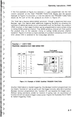
Page 44: ...nnel will then qualify the product only at the selected rising or falling EDGE sensitive channel transition Figure 2 5 shows a simple example of a product consisting of CH1 and CH2 where CH2 is select...

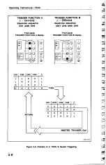
Page 45: ...ystroke sequence NOT CH3 AND CH4 Front panel TRIGGER FUNCTION A display Front panel TRIGGER FUNCTION B display CH1 CH2 CH3 CH4 fa L L X X L L H X X L H L X X L H H X X H THEN RETURN CH1 CH2 CH3 CH4 f...

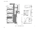
Page 46: ...red for the normal operation of the 7A42 Logic Triggered Vertical Amplifer unit are located on the front panel Figure 2 7 shows an exploded front panel and gives a brief functional description of each...

Page 47: ......

Page 48: ...hannel selected by controls listed under number 61 1M 50 Pushbutton switch selects input impedance to be either one megohm or 50 ohms of the channel selected by controls listed under number 61 TTL ECL...

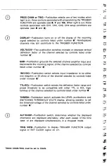
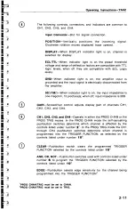
Page 49: ...en off input impedance is 50 GAIN Screwdriver control adjusts display gain of channels CH1 CH2 CH3 and CH4 CH1 CH2 CH3 and CH4 Operate in either the PROG CHAN or the PROG TRIG modes In the PROG CHAN m...

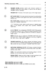
Page 50: ...to arm triggering before B is allowed to produce a trigger output RESET External input to disable the TRIGGER FUNCTION output and disarm the A THEN B nested triggering no arming or triggering can occu...

Page 51: ...E 1 PRELIMINARY SET UP AND INITIALIZATION This exercise describes proper installation of the 7A42 into a compatible oscilloscope mainframe exercises the self test sequence and initializes the front pa...

Page 52: ...n mentioned in the text INITIALIZATION After completion of the 7A42 installation and power up self test sequence the next step is to initialize the 7A42 front panel settings To initialize the 7A42 fro...

Page 53: ...nstructions 7A42 d Turn the oscilloscope mainframe Power off and then on again e After the self test is completed the 7A42 front panel status indicators and control lights should be as shown below 428...

Page 54: ...stration of the 7A42 front panel GAIN adjustment and how to obtain a triggered display on each of the four channels is also given NOTE If continuing from Exercise 1 proceed with Exercise 2 If not firs...

Page 55: ...2 Observe that the TRIGGER FUNCTION has been set to trigger on a HI level of CH1 3 Rotate the CH1 POSITION control 4 to move the triggered display to the center of the crt Press the upper VOLTS DIV pu...

Page 56: ...trace 11 is now displayed at the bottom of the crt TRIG VIEW pushbutton is illuminated 12 Rotate the CH1 POSITION control 13 and notice that it has no affect on the trigger view display 11 Set the CH...

Page 57: ...and that the CH1 waveform 19 and TRIG VIEW waveform 20 are replaced by a baseline trace the CH1 input is now referenced to ground Press the GND pushbutton 21 again The CH1 GND indicator 22 is now ext...

Page 58: ...igger mode has been selected Press the CLEAR pushbutton 26 and notice that the CH1 TRIGGER FUNCTION indicator 27 extinguishes the CH1 display 28 free runs is not triggered and the TRIG VIEW waveform 2...

Page 59: ...HI trigger level Both the CH1 waveform 32 and the TRIG VIEW waveform 33 are again triggered Press the NOT pushbutton 34 Notice that the CH1 TRIGGER FUNCTION light 35 is now green and that the CH1 disp...

Page 60: ...control clockwise to view the trace Press the EDGE pushbutton 40 Notice that the CH1 TRIGGER FUNCTION light is flashing to indicate edge qualified triggering and that the display is triggered on the r...

Page 61: ...ling edge of CH1 45 and the CH1 TRIGGER FUNCTION indicator 46 is now flashing green Press the EDGE pushbutton 47 the display is now triggered on the LO level of CH1 48 The CH1 TRIGGER FUNCTION indicat...

Page 62: ...ess the AND pushbutton 53 then press the CH2 pushbutton 54 and notice that the CH2 TRIGGER FUNCTION indicator 55 illuminates red CH1 56 remains red Notice also that the CH1 display is not triggered 57...

Page 63: ...ions 7A42 Press the CLEAR pushbutton 58 the CH1 and CH2 TRIGGER FUNCTION indicators 59 extinguish Press the CH1 pushbutton 60 The TRIGGER FUNCTION requirements are now met and the CH1 display is again...

Page 64: ...63 If necessary adjust the 7A42 GAIN 64 front panel screwdriver adjustment for exactly 2 divisions of display position display as necessary Select CH2 for display by first pressing the CH2 pushbutton...

Page 65: ...lay 72 is free running because there is no TRIGGER FUNCTION 73 selected for CH2 and therefore the time base unit does not receive a trigger signal A base line trace is now displayed 74 for CH1 The bas...

Page 66: ...adout 78 are no longer displayed To set the TRIGGER FUNCTION requirements for CH2 first select the Program Trigger mode by pressing the PROG pushbutton 79 so that it is lit green Press the CLEAR pushb...

Page 67: ...ER FUNCTION indicator denotes an active LO trigger level Notice that the CH2 display 87 is triggered on the LO level of the calibrator signal Press the NOT pushbutton 88 again and observe that the TRI...

Page 68: ...V as displayed on the crt readout 94 Check the CH2 display for a 2 division square wave display 95 To remove the CH2 display from the crt press the DISPLAY pushbutton 96 Notice that the CH2 DISPLAY in...

Page 69: ...nger displayed Select CH3 for display by first pressing the CH3 pushbutton 103 and then the DISPLAY pushbutton 104 Notice that the CH3 DISPLAY indicator 105 is illuminated red and that the CH3 deflect...

Page 70: ...ton 110 Notice that the CH3 TRIGGER FUNCTION indicator 111 illuminates red Notice that the CH3 display 112 is triggered and that a TRIG VIEW signal 113 is displayed Change the vertical deflection fact...

Page 71: ...or 1 20 to the CH4 input connector 121 Observe that the channel 4 display 122 is not triggered The CH4 display is not triggered because no TRIGGER FUNCTION requirements have been selected for CH4 and...

Page 72: ...pushbutton 126 To set TRIGGER FUNCTION requirements for CH4 press the PROG pushbutton 127 Program Trigger mode Then remove the CH3 TRIGGER FUNCTION by pressing the CLEAR pushbutton 128 Now press the...

Page 73: ...or 132 press the PROG pushbutton 133 so that the light is extinguished Press the CH4 pushbutton 134 and then press the upper VOLTS DIV pushbutton 135 once for 0 2V as displayed on the crt readout 132...

Page 74: ...ce any Tektronix 7000 series time base or oscilloscope any Tektronix 10X voltage probe and any pulse generator with both a trigger output and a delayable pulse output capable of producing zero to 2 vo...

Page 75: ...ER SOURCE LEFT VERT PULSE GENERATOR PERIOD 2 S DELAY 0 1 S VARIABLE DELAY CAL DURATION 0 1 S VARIABLE DURATION CAL TRANSITION TIME 5 nS TRIGGERING FREERUN MODE DELAYED TIME BASE TIME DIV 500 nS DIV TR...

Page 76: ...CRT readout 2 Use the CH1 POSITION control 4 as necessary to move the square wave 3 approximately 2 5 divisions in amplitude so that it can be viewed on the ert Press the GND pushbutton 5 and notice...

Page 77: ...tton light on Press and hold the 7A42 LEVEL control 13 and notice that the SWITCHING THRESHOLD display 14 increases from the default setting of 1 4 V Notice that when the SWITCHING THRESHOLD display r...

Page 78: ...4 V The CH1 deflection factor also defaults to 5 V division 19 the minimum display size available Press the CH4 pushbutton 20 then press the DISPLAY pushbutton 21 Notice that the CH4 pushbutton 20 an...

Page 79: ...he second horizontal graticule line up from the bottom of the crt 27 This is the CH4 ground reference Press the GND pushbutton 28 again and notice that the CH4 waveform is again displayed 29 Notice th...

Page 80: ...d CH4 displays by varying the pulse generator Variable Delay control Notice that during the time that the CH 1 39 and the CH4 40 displayed waveforms are both HI that the TRIG VIEW display is HI 41 Set...

Page 81: ...y is double triggered A stable trace can now be obtained by using the 7A42 TRIGGER FILTER control Rotate the TRIGGER FILTER control 48 clockwise until the narrower of the two TRIGGER VIEW pulses 49 di...

Page 82: ...time base Time Div to 100 ns 54 Notice that the TRIG VIEW display has a narrow pulse 55 coincident with the rising edge 56 of the CH4 display Press the NOT pushbutton 57 Observe that the displayed TR...

Page 83: ...h of 100 ns CAL position Set the time base Time Div control to 500 ns Set the pulse generator to Both Paired by pressing both the Delayed and Undelayed pushbuttons together Set the pulse generator Var...

Page 84: ...ator Delay control and notice that a trigger is displayed on the TRIG VIEW trace 76 while the CH4 pulse 77 is HI regardless of the CH1 signal 78 being HI or LO Set the pulse generator Variable Delay c...

Page 85: ...the pulse generator Delay control notice that a trigger occurs on the TRIG VIEW trace 81 only on the leading edge of the first CH4 pulse 82 following the falling edge of the CH1 trace 83 The display...

Page 86: ...ectors may cause a Self Test failure When power is applied to the 7A42 an internal self test sequence is automatically performed While the self test sequence is in progress the mainframe crt readout s...

Page 87: ...displayed for a few seconds before the self test is completed Self test failures are indicated by three different methods 1 on the mainframe crt 2 on the 7A42 SWITCHING THRESHOLD display and 3 on the...

Page 88: ...est sequence press any of the 7A42 front panel pushbuttons NOTE There should be no connections to the RESET EXT CLOCK and TIP Inputs during the time Self Test is running NOTE Before the 7A42 Self Test...

Page 89: ...to 09 Micro processor control logic CH4 first column PROBE OFFSET 10 PROBE OFFSET Avoid use of probe offset feature 7A42 otherwise fully functional Repair when convenient CH1 second column Crt displa...

Page 90: ...nal clock Repair when convenient CH4 second column EXT CLOCK 70 EXT CLOCK Avoid use of external clock Repair when convenient FRONT PANEL INITIALIZATION While getting acquainted with the 7A42 it might...

Page 91: ...set to 0 5 V Div at bnc input TTL ECL CH1 through CH4 TTL GND CH1 through CH4 Ungrounded 1M 50 CH1 through CH4 1M ALT CHOP ALT TRIG VIEW Off SWITCHING THRESHOLD voltage CH1 though CH4 Preset TTL 1 4V...

Page 92: ...d OPERATOR MESSAGES Operator Messages occur under several operating conditions and are accompanied by an audible beep When they occur the mainframe readout will display a mnemonic at the top of the CR...

Page 93: ...erator keys AND or OR were pressed without pressing a channel key CH1 CH2 CH3 or CH4 in between Channel keys and Boolean operator keys should be pressed alternately e g CH1 AND NOT CH2 OR CH3 EDGE 7 O...

Page 94: ...ate out of range A beep will sound when the VOLTS DIV keys are pushed beyond the available selections or when the variable threshold level reaches its limits NOTE The audible beep can be turned off re...

Page 95: ...31 probe manual for high frequency compensation adjustment procedure COAXIAL CABLES Although the 7A42 input channel VOLT DIV ranges are intended to be used with 10X probes coaxial cables may be used f...

Page 96: ...Operating Instructions 7A42 Figure 2 13 Channel readout display Figure 2 14 Channel readout display with 10X probes attached to Inputs of CH1 CH2 CH3 and CH4 2 58 REV JUL 1984...

Page 97: ...annel is displayed on the mainframe crt If the indicator is extinguished any signal applied to the channel input will still be routed to the TRIGGER FUNCTION circuitry providing the GND indicator is n...

Page 98: ...logical AND function a Boolean product of the four input channels After the AND functions are performed the columns are ORed together to form the complete Boolean TRIGGER FUNCTION Thus each TRIGGER F...

Page 99: ...cause a triggered sweep as well as a signal at the front panel TRIG OUT connector The TRIGGER FILTER control can be used only with level sensitive trigger functions it is inactive with any TRIGGER FU...

Page 100: ...tly connected to the logic circuit in either TTL or ECL mode 10X probes should not be used with this input RESET INPUT The RESET INPUT allows the operator to apply a signal to inhibit the trigger outp...

Page 101: ...Two modes of operation can be selected for the TRIGGER Out connector Normal and A THEN B Gate In Normal Mode the A THEN B Trigger Out is a pulse regardless of the duration of Trigger Function B A typ...

Page 102: ...d with the CH1 CH2 CH3 and CH4 pushbuttons to individually set the channel status In the PROG TRIG mode CLEAR AND OR NOT and EDGE pushbutton controls are activated and are used with the CH1 CH2 CH3 an...

Page 103: ...20 50 100 mV Div 2 5 1 V Div GND The GND pushbutton connects the selected channel amplifier input to ground as a reference for trace positioning However the incoming signal is not grounded it is disco...

Page 104: ...n be adjusted to any other value independent of the probe offset by using the LEVEL buttons Pressing the PROBE OFFSET button once more turns off the lit button clears the acquired offset measurement a...

Page 105: ...n the Boolean TRIGGER FUNCTION For example if CH1 is entered into the TRIGGER FUNCTION display that is CH1 is an active HI red pressing the NOT key will change it to an active LO green Successively pr...

Page 106: ...ge sensitive channel will become level sensitive only This is because only one edge sensitive channel per product is allowed If the last entered channel is converted back to level sensitive the previo...

Page 107: ...easurements and single key waveform parameter measurements to save time and improve both accuracy and resolution When gated by the 7A42 the 7D15 Universal Counter Timer can provide a numerical readout...

Page 108: ...DGE SENSITIVITY TO YOUR TRIGGER FUNCTION 3 6 APPLICATION 4 DETECTING AND DISPLAYING BUS CONTENTION 3 9 APPLICATION 5 ENHANCED NESTED TRIGGERING USING THE 7D15 225 MHz UNIVERSAL COUNTER TIMER 3 11 APPL...

Page 109: ...n example of viewing the output of a counter when the countdown reaches a value of decimal 10 where the LSB is displayed on the CH1 trace and the MSB is displayed on the CH4 trace To accomplish this e...

Page 110: ...tration accuracy of the Trigger View trace with the channel display s makes it useful in verifying when the programmed trigger condition indeed exists The Trigger View trace can also be used to measur...

Page 111: ...or negative transition of the external clock input signal and 2 display that clock signal by selecting the Trigger View trace Figure 3 2 Display of four channels with TRIG VIEW trace Figure 3 3 Four...

Page 112: ...idually in this manner MEASUREMENT TECHNIQUE When one wants to trigger on a pulse that is somewhere in the TTL threshold region 0 8V and 2 0V a problem arises because the pulse is too low to be recogn...

Page 113: ...ations 7A42 Figure 3 4 Triggering on a low amplitude puise prevent triggering on these normal transitions and at the same time allow the low amplitude pulse of a slightly longer duration to be detecte...

Page 114: ...h and low levels the 7A42 can incorporate one edge sensitive channel into each product AND function Because each Trigger Function A or B can contain two products two independent Edge operators per Tri...

Page 115: ...t occurrs 140 nanoseconds into the next read cycle because that data transition falls within the time that the data may still change Trigger Function A arms when a low level Read strobe occurs after t...

Page 116: ...Applications 7A42 Figure 3 6 Set up to monitor invalid data transitions Figure 3 7 The 7A42 captures a positive transition of data during the time data should be stable 3 8...

Page 117: ...glitch This fault condition is very difficult to detect with an ordinary oscilloscope due to the aperiodic nature of bus activity Also the level and slope triggering system of a conventional oscillosc...

Page 118: ...Applications 7A42 Figure 3 8 Bus contention measurement set up 3 10...

Page 119: ...Trigger Function B The 7D15 will also function as a gated events counter capable of counting the number of cycles between Trigger Function A and Trigger Function B or as an events counter to provide...

Page 120: ...stics and enter the following 7D15 and mainframe settings 7D15 Settings Connect clock signal from the unit under test to the 7D15 B input Gate CH A Gate Mode Freq B Display Time 0 1 sec Storage Off Tr...

Page 121: ...ttings Gate Normal Mode TIM Width A Averg X10 Clock 10 ns Trigger A Source Trigger Source Slope Coupling DC Level Preset Mainframe Settings Set the Trigger Source for the compartment containing the 7D...

Page 122: ...es a built in 50 ohm termination resistor that can be switched in for use with 1 megohm amplifiers This 50 ohm termination will be switched out in this application in favor of the 7A42 s internal 50 o...

Page 123: ...to ground would form a voltage divider with the gate s output termination resistor Figure 3 9 shows an ECL emitter follower output stage being probed a by a standard 500 probe and b by the P6230 Varia...

Page 124: ...he probe offset to the desired voltage While holding the probe tip in the jack push the PROBE OFFSET button again until it lights green The offset forthat particular channel has now been measured acqu...

Page 125: ...ional mode for the 7854 There is an internal jumper that must be properly positioned by qualified service personnel as detailed in the 7A42 Service Manual This ensures that readout and waveform acquis...

Page 126: ...4 trace is much brighter than conventional oscilloscopes High transition pulses at low speed duty cycles can be easily seen under normal lighting conditions without the annoying baseline blooming as o...

Page 127: ...N FOUR INSTRUMENT OPTIONS No options existed for the 7A42 at the time of this printing Information about any subsequent options will be included in the CHANGE INFORMATION section at the back of this m...

Page 128: ...of 2 60 Illustration of 2 64 ACCESSORIES Optional 1 24 Standard 1 24 ALT Brief description of 2 10 Detailed description of 2 60 AND Boolean definition of 2 3 Brief description of 2 10 Detailed descri...

Page 129: ...0 2 11 2 12 CONTROLS Front Panel 2 10 CRT READOUT 2 57 D DEFLECTION FACTOR 2 65 DELIMITER 2 67 DeMORGAN S THEOREM 2 4 DISPLAY 2 10 2 59 2 65 Specification of 1 6 DOCUMENTATION RELATED 1 1 DVM 2 66 E E...

Page 130: ...IONAL CIRCUIT BLOCKS 2 1 G GAIN 2 11 2 59 GET ACQUAINTED EXERCISES 2 13 GND 2 10 2 59 2 65 INPUT 1M 2 10 2 59 2 65 50 2 10 2 59 2 65 INSTALLATION 2 13 INTIALIZATION 2 14 2 52 Control Settings 2 53 L L...

Page 131: ...OG CHAN 2 10 PROG CHAN TRIG 2 10 2 64 PROG TRIG 2 10 PROGRAM CHANNEL MODE 2 10 2 64 PROGRAM TRIGGER MODE 2 10 2 66 P6131 1 24 2 57 P6230 1 24 2 57 2 66 3 14 3 15 P6230 VARIABLE BIAS OFFSET 3 14 R READ...

Page 132: ...12 TIME FROM FUNCTION A TO FUNCTION B 3 12 TIP PROBE OFFSET 2 66 TRIG VIEW 2 10 3 2 TRIGGER FILTER 2 12 2 61 3 7 Application of 3 4 TRIGGER FUNCTION 2 12 Color red HI green LO 2 60 TRIGGEERING NESTED...

Page 133: ...lope key was pressed when the EXT CLOCK SYNC button was turned off The EXT CLOCK SYNC slope key is operational only when the EXT CLOCK SYNC button is turned on 10 EDGE IS ON The EXT CLOCK SYNC key was...

Reviews: