


C
L E A R
P
A T H
- S C
U
S E R
M
A N U A L
R
E V
.
1 . 3 6
5 6
T
EKNIC
,
I
NC
. T
EL
.
(585)
784-7454
S
COPE
D
ISPLAY AND
S
COPE
C
ONTROLS
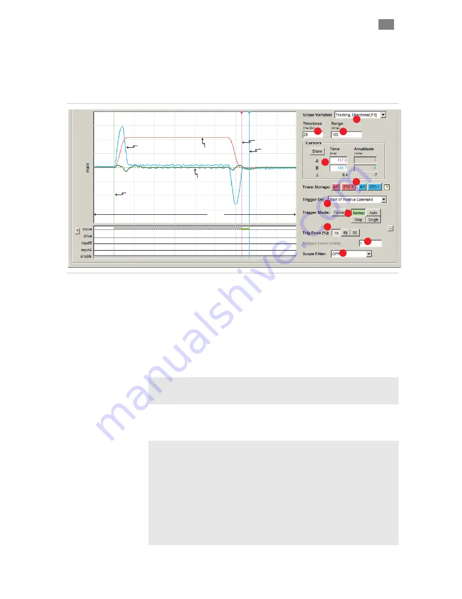
The ClearView Scope display is modeled after a typical hardware
oscilloscope. It has 10 major vertical divisions (the time axis), and 8 major
horizontal divisions (the amplitude axis).
Stored Trace (STO 1)
Actual Torque
Cursor A
Trigger Point
Currently at 10% position
Stored Trace (STO 0)
Commanded Velocity
Live Trace
Tracking Error
100mS
(10 mS/division x 10 divisions)
Cursor B
Click and drag
to position cursors
2
3
4
5
6
7
1
8
9
10
ClearView Soft Scope
1
The Scope Variable drop down menu lets you select any of 13
ClearPath-SC motion control variables to display. These variables are
Tracking Error, Commanded Velocity, Actual Torque, Actual Velocity,
Velocity Error, Commanded Torque, SGN (sign of velocity), Measured
Position, Commanded Jerk, Commanded Acceleration, Max Phase
Voltage, Torque Error (peak), and Bus Voltage.
2
The Timebase field lets you adjust the scale of the time axis (think X-
axis) in units of mS/division. This allows you to control how a waveform
fits horizontally on the Scope Display.
Example: With the Timebase set to 10mS per division (as in the figure
above) the full horizontal range of the Scope Display is 100mS (10
divisions x 10mS/division).
3
The Range field lets you adjust the scale of the amplitude axis (think
Y-axis). This allows you to control how a waveform fits vertically on the
Scope Display.
Example: In the figure above, the green "live" trace represents the
motor's tracking error (i.e. how close is the actual motor position to the
commanded position). The Range is set to 100 counts.
To interpret the displayed information, you only need to understand a few
things: 1) the center horizontal line represents 0 counts of tracking error
(perfect tracking), 2) the top of the Scope Display repr100 counts
of tracking error, and 3) the bottom of the scope display represents -100
counts of tracking error. The +/- distinction is necessary because the
actual motor position can lead or lag the commanded position. By doing a
little math you will find that each major horizontal division represents 25
counts of error.


