6
INSTALLATION
TECHNICAL INFORMATION
FOR THE INSTALLER
Installation, adjustments of controls and
maintenance must only be carried out by a
qualified engineer.
The appliance must be correctly installed in
conformity with current law and the
manufacturer's instructions.
Incorrect installation may cause damage to
persons, animals or property for which the
Manufacturer shall not be considered
responsible.
During the life of the system, the automatic
safety or regulating devices on the appliance
may only be modified by the manufacturer or
by his duly authorized dealer.
3) INSTALLING THE HOT PLATE
Check that the appliance is in a good condition
after having removed the outer packaging and
internal wrappings from around the various loose
parts. In case of doubt, do not use the appliance
and contact qualified personnel.
Never leave the packaging materials
(cardboard, bags, polystyrene foam, nails, etc.)
within children’s reach since they could
become potential sources of danger.
The measurements of the opening made in the top of
the modular cabinet and into which the hot plate will
be installed are indicated in either fig. 7. Always
comply with the measurements given for the hole into
which the appliance will be recessed (see fig. 7 and 8).
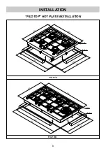
The filotop model needs of a milling on the plan
top of depth 3 mm, measures are shown in figures
10/A and 10/B of next page. It is advisable to
spread on the milled surface a layer of "primer"
anti-infiltration.
The appliance belongs to class 3 and is
therefore subject to all the provisions
established by the provisions governing such
appliances.
4) FIXING THE HOT PLATE
The hot plate has a special seal (in the case of
filotop) or putty (in the case of semifilo) which
prevents liquid from getting into the cabinet.
Strictly comply with the following instructions in
order to correctly apply this seal:
- detach the seals (or putty) from their backing,
checking that the transparent protection still
adheres to the seal (or putty) itself.
- Overturn the hot plate and correctly position seal
(or putty) “E” (fig. 9) under the edge of the hot
plate itself, so that the outer side of the seal (or
putty) perfectly matches the outer edge of the
hot plate. The ends of the strips must fit together
without overlapping.
- Evenly and securely fix the seal (or putty) to the
hot plate, pressing into place with the fingers and
remove the strip of protective paper from the seal
(or putty) and set the plate into the hole made in
the cabinet.
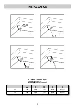
- To insert the hooks “G” into the fissures on the
bottom and rotate them according to the arrow
indicationts. To insert the screw “F” into the
bottom holes and turn thoroughly the screws “H”
on the hooks holes (see the sequence on the
next page).
- In order to avoid accidental touch with the
overheating bottom of the hob, during the
working, is necessary to put a wooden insert,
fixed by screws, at a minimum distance of 120
mm from the top (see fig. 7).
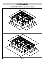
- To follow the installation measures shown in
figures 10/A, 10/B and 11/A, 11/B.
FIG. 7
FIG. 8
FIG. 9
IMPORTANT!
A perfect installation, adjustment or
transformation of the cook top to use
other gases requires a QUALIFIED
INSTALLER: a failure to follow this rule will
void the warranty.
Summary of Contents for EW 90 5G AI AL TR CI E1-ME
Page 9: ...9 INSTALLATION SEMIFILO HOT PLATE INSTALLATION FIG 11 A FIG 11 B ...
Page 25: ...25 INSTALLATION INSTALLATION DE CUISSON OU GAZ SEMIFILO FIG 11 A FIG 11 B ...
Page 40: ...9 التﺮكيﺐ تركيب موقد سيمي فيلو الشﻜﻞ 11 A الشﻜﻞ 11 B ...
Page 41: ...8 التﺮكيﺐ تركيب موقد فيلوتوب الشﻜﻞ 10 A الشﻜﻞ 10 B ...
Page 49: ......
Page 50: ......
Page 51: ......
Page 52: ......
Page 53: ......
Page 54: ......
Page 55: ......
Page 56: ......
Page 57: ......
Page 58: ......
Page 59: ......
Page 60: ......
Page 61: ......
Page 62: ......
Page 63: ......
Page 64: ......
Page 65: ......
Page 66: ......
Page 67: ......
Page 68: ......
Page 69: ......
Page 70: ......
Page 71: ......
Page 72: ......
Page 73: ......
Page 74: ......
Page 75: ......
Page 76: ......


