background image

51

Code N

º

: PRM-00-0001

Revised / Date

: 2006

I

NSTALLER

M

ANUAL 

Page N

º

: 51 of 95

8) Adapt the combination of the lower tube cover

(A9)

and the upper tube cover

(A8)

to the

lower part of the of the internal structure

(A7)

and the decorative extra piece

(U).

9) Fit the whole of the combined lower piece to the upper piece and mount on the ceiling with

the screws provided

(A10)

(M4 x 12), to the desired height.

10) Connect the upper part of the inner tube (not included) to the exit.
11) Lift the upper tube cover

(A8)

and secure it to the upper part with the supplied screws

(G)

(M4 x 12), with a conical head.

12) Adjust the decorative supplementary piece

(U)

, securing it to the hood with the screws

(V)

(M4) supplied with the piece.

Summary of Contents for CL 90

Page 1: ...ation and evacuation of gases The appliance should be connected to the mains supply via a suitable omnipolar switch with a 3 mm miminum gap between contacts Do not connect the appliance to ducts used for the evacuation of gases of a non electrical nature such as boilers chimneys etc Do not start up the appliance if the mains cable or control panel appear to be damaged in any way Once the apparatus...

Page 2: ...44 Code Nº PRM 00 0001 Revised Date 2006 INSTALLER S MANUAL Page Nº 44 of 95 Model Dimensions ISLA ND ALADA ISLA DS ISLA ...

Page 3: ...45 Code Nº PRM 00 0001 Revised Date 2006 INSTALLER S MANUAL Page Nº 45 of 95 Model Dimensions CL 90 DX 90 ASYMETRIC DA 90 ...

Page 4: ...46 Code Nº PRM 00 0001 Revised Date 2006 INSTALLER S MANUAL Page Nº 46 of 95 Model Dimensions DS 60 1 70 90 DI 70 90 110 DM 60 70 90 ...

Page 5: ...47 Code Nº PRM 00 0001 Revised Date 2006 INSTALLER S MANUAL Page Nº 47 of 95 Model Dimensions DE 60 2 70 2 90 2 ND ALADA 70 90 CONICAL DC 60 70 90 ...

Page 6: ...48 Code Nº PRM 00 0001 Revised Date 2006 INSTALLER S MANUAL Page Nº 48 of 95 Model Dimensions RUSTIC DR 90 Model Dimensions DF 90 ...

Page 7: ...001 Revised Date 2006 INSTALLER S MANUAL Page Nº 49 of 95 DP DH DAL Accessories supplied with decorative hoods 150 125 mm adaptor Anti return valve Support for tube cover Support for wall mounting Screws Rawlplugs Washers ...

Page 8: ...he corresponding screws S 3 Place the upper part of the internal structure A6 on the support O with screws Q M6x16 4 Adjust the decorative supplementary piece U carefully securing it with the screws V M4 supplied with the piece 5 Insert piece B if the interior tube not supplied has a diametre of 120 mm 6 Secure the interior tube with a jubilee clip not supplied to B or on the exit section of the m...

Page 9: ...it the whole of the combined lower piece to the upper piece and mount on the ceiling with the screws provided A10 M4 x 12 to the desired height 10 Connect the upper part of the inner tube not included to the exit 11 Lift the upper tube cover A8 and secure it to the upper part with the supplied screws G M4 x 12 with a conical head 12 Adjust the decorative supplementary piece U securing it to the ho...

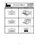
Page 10: ...52 Code Nº PRM 00 0001 Revised Date 2006 INSTALLER S MANUAL Page Nº 52 of 95 ND ALADA ISLA DS ISLA DX 90 ...

Page 11: ...53 Code Nº PRM 00 0001 Revised Date 2006 INSTALLER S MANUAL Page Nº 53of 95 ASYMETRIC DA 90 DS 60 1 70 90 DI 70 90 110 ...

Page 12: ...54 Cód PRM 00 0001 Revised Date 2006 INSTALLER S MANUAL Page Nº 54 of 95 DM 60 70 90 ND ALADA 70 90 DE 60 2 70 2 90 2 ...

Page 13: ...55 Code Nº PRM 00 0001 Revised Date 2006 INSTALLER S MANUAL Page Nº 55 of 95 CONICAL DC RUSTIC DR 90 ...

Page 14: ...ctor motor making sure that the filter openings A coincide with the pivots B of the motor housing Turn in the direction as shown in the diagram 2 Remove the tube covers E Place the sheet C on the air outlet section of the motor 3 Replace the tube covers E 5 2 2 SET Type 2 1 Attach the nut to the support F on the hood body 2 Secure the supports B with the screws E to the nuts F 3 Fit the carbon fil...

Page 15: ...57 Code Nº PRM 00 0001 Revised Date 2006 INSTALLER S MANUAL Page Nº 57 of 95 NEW RECIRCULATION KITS FROM JANUARY 2006 ...

Page 16: ... mains supply via a suitable omnipolar switch with a 3 mm miminum gap between contacts Do not connect the appliance to ducts used for the evacuation of gases of a non electrical nature such as boilers chimneys etc Do not start up the appliance if the mains cable or control panel appear to be damaged in any way Once the apparatus has been fitted ensure that the mains cable does not come into contac...

Page 17: ...59 Code Nº PRM 00 0001 Revised Date 2006 INSTALLER S MANUAL Page Nº 59 of 95 Model Dimensions C620 C 901 GF 2 ...

Page 18: ...60 Code Nº PRM 00 0001 Revised Date 2006 INSTALLER S MANUAL Page Nº 60of 95 Model Dimensions CNL 1001 2002 ...

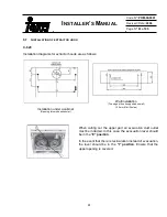
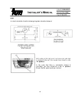
Page 19: ...lation under a cabinet Opening for smoke exhauster When cutting out the upper part an evacuation duct outlet must be included In this case the evacuation lever should be in the E position In the event that there is recirculation instead of evacuation the lever should be in the I position Ensure that the upper opening is covered Wall installation Top edge of hood supported on wall 2 5 mm Ø drill ho...

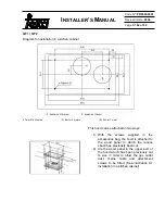
Page 20: ...od can be attached in two ways 1 With the screws supplied in the accessories bag the hood is attached to the wood panel in which the recess space has previously been cut 2 Via the wood panel in the upper part of the hood which has been previously cut to size in order to allow the gas outlet duct mains cable and attachment screws to be fitted See illustration for installation in a kitchen cabinet ...

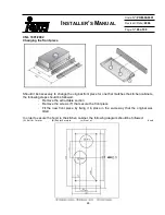
Page 21: ...required to change the original front piece for one that matches the kitchen cabinets the following steps should be followed Remove the extractable section Remove the screws T that secure the front piece Fit the new front piece by fixing it in place in the same way as the original was fitted ...

Page 22: ...supported on wall Opening for outlet duct Centre of the cooker Wall installation Top edge of the hood Centre of the cooker When cutting out the upper part an evacuation duct outlet must be included In this case the evacuation lever should be in the E position In the event that there is recirculation instead of evacuation the lever should be in the I position Ensure that the upper opening is covere...

Page 23: ...t matches the kitchen cabinets the following steps should be followed Remove the extractable section Remove the screws T that secure the front piece Fit the new front piece by fixing it in place in the same way that the original was fitted In order to secure the hood to the kitchen cabinet the following diagram should be followed A Exit for 1 motor B Exit for 2 motors c Front of hood ...

Reviews: