62
Code N
º
: PRM-00-0001
Revised / Date
: 2006
I
NSTALLER
’
S
M
ANUAL
Page N
º
: 62 of 95
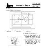
GF1 / GF2
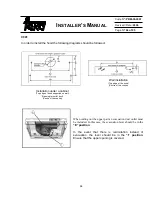
Diagram for installation in a kichen cabinet
4 7 mm
Ø
drill holes
(A) Exit for 2 motors
(B) Exit for 1 motor
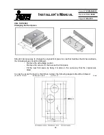
This hood can be attached in two ways:
1) With
the
screws
supplied
in
the
accessories bag, the hood is attached to
the wood panel in which the recess
space has previously been cut.
2) Via the wood panel in the upper part of
the hood which has been previously cut
to size in order to allow the gas outlet
duct, mains cable and attachment
screws to be fitted. (See illustration for
installation in a kitchen cabinet).


