Teikoku USA | Chempump
Instruction Manual G-Series
14
2.3.5 Oil Filled Stator
G-Series pumps are designed to provide long, trouble free service
with oil filled stator cavities provided as standard. Solid filled or
dry stator options are available for many applications. In order to
facilitate even dissipation of heat from the motor section, elimi-
nate operating hot spots on the motor winding and promote lon-
ger motor life, the stator cavity on standard G-Series pumps is
factory filled with a heat conductive dielectric oil. Inert oils are also
available. Oil filling provides enhanced conductivity and allows the
heat generated in the motor to be conducted to the outside of
the unit, thereby maintaining a lower temperature in the motor
section than would be possible with a dry stator. When storing or
installing oil filled stators, be sure that the motor lead or connec-
tion box nipple is maintained in an upright vertical position. Refer
to
Table 2-7
for oil volume in G Series stators.
2.4 Special Conditions and Features
2.4.1 Back-Flushing (Plan 32-S)
For normal, clean fluid applications, G-Series pumps are cooled
and lubricated by the fluid being pumped (Plan 11-S). For slurry
and other “dirty” applications, a system of back-flushing is rec-
ommended.
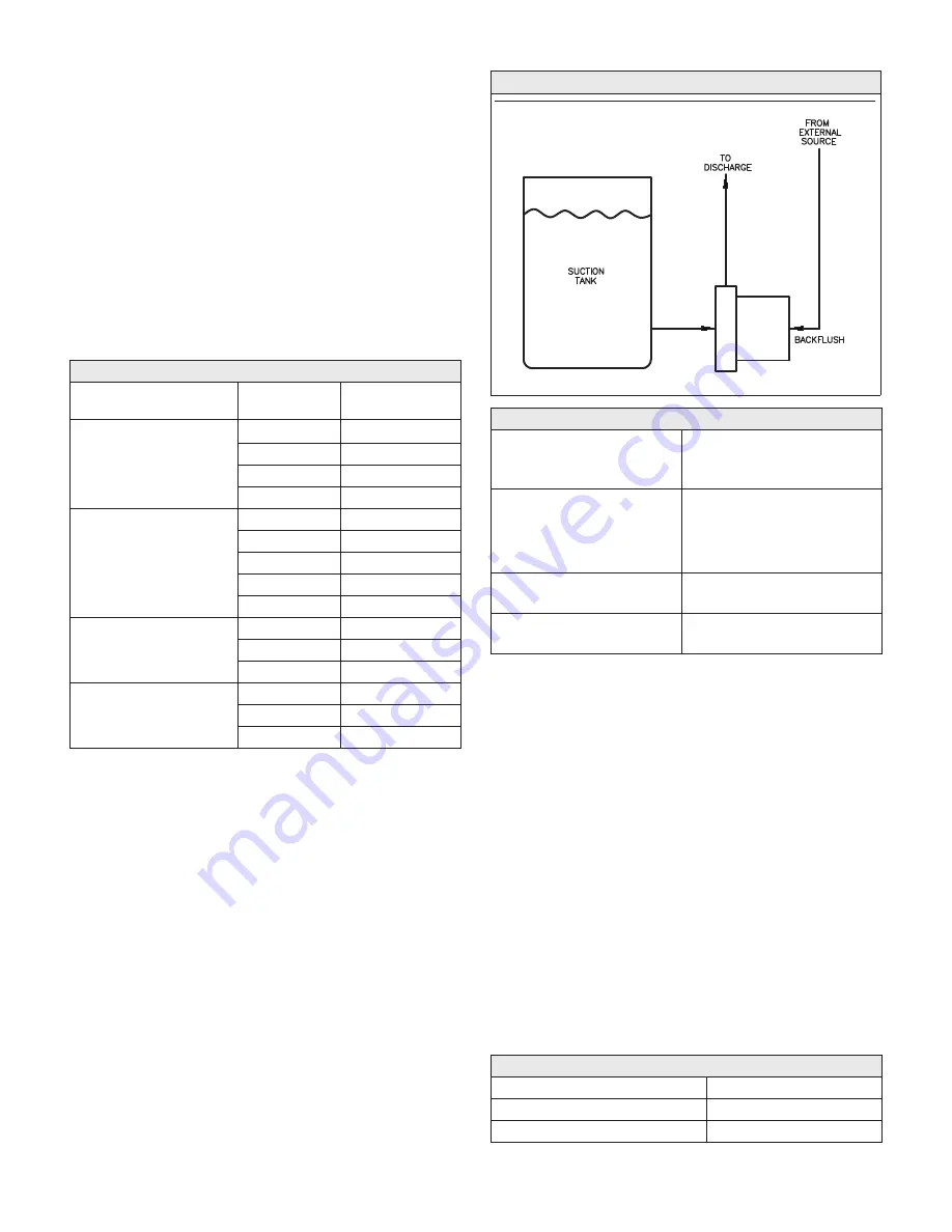
Back-flushing is noted on the order when recommended. See
Fig-
ure 2-3
for a typical back flush installation.
Pumps to be used with back-flush are normally supplied without
circulating tubes. Clean fluid is brought to the fitting at the rear
bearing housing using the customer’s piping as shown in
Figure
2-3
. The amount of clean base fluid introduced in this manner
should approximate the standard flow rates listed in
Table 2-8
,
below.
Table 2-7. Oil Volume in G-Series Stators
G-Series
Model
Motor
Size
Volume of Oil
(Fluid Ounces)
GA
GA, GB, GC
GB, GC, GVBS, GLD
GB, GC, GVBS, GLD
1K
41.5
1-1/2K
42
3K
44
5K
45
GVD, GVE, GVHS, GG
GVD, GVE, GVHS, GG
GVD, GVE, GVHS, GG, N2S
GVD, GVE, GVHS, GG, N2S
GVD, GVE, GVHS, GG, N2S
5K
90
7-1/2K
90.5
10K
91
15K
92
20K
93
GVM
5P, 7-1/2L
95
10L
95
15
95
N2S
30K
130
40K
130
50K
130
Table 2-8. Standard Recirculation Flow Rates
Model
Recirculation
Flow Rate
(gpm)
GA
GB
GC
GVBS
1 to 2
1-1/2 to 2-1/2
1-1/2 to 2-1/2
1-1/2 to 2-1/2
GVD, GVE, GVHS
GG
2 to 4
1-1/2 to 3
GVM
GLD
1 to 3
4 to 5
Back-flush pressure should be suction pressure plus 20-30% of
the pressure developed by the pump itself for single stage Models
GA, GB, GC, GVBS, GVD, GVE, GVHS, GG and GVM, and suction
pressure plus 60-80% of the pressure developed by the pump
itself for two stage Model GLD. Excessive back-flush pressure will
destroy the thrust balanced operation built into G-Series pumps
by causing excessive forward thrust.
Procedure:
1. Remove the circulation tube and plug the port in the discharge
neck of the pump casing used for the circulating tube front fit-
ting. (This is done at the factory).
2. Pipe in the clean liquid to the port in the rear bearing housing
used for the circulating tube rear fitting. See
Table 2-9
below
for proper circulating tube sizes.
3. If the back-flushing liquid is hot, auxiliary cooling methods,
such as water jacketing the stator must be employed. The tem-
perature of the back-flush fluid should not be close to its boil-
ing point and should not exceed 300˚ Fahrenheit.
Table 2-9. Circulating Tube Sizes
Model
Tube Size
GA, GB, GC,GVBS, GLD
1/4" O.D. x 0.035 Wall
GVD, GVE, GVHS, GG, GVM, N2S
3/8" O.D. x 0.035 Wall
Figure 2-3. Back-Flush System


