background image

57

98-05273-EN R7

MATRIX

®

 Pro 570GS • MATRIX

®

 Pro840GS

HOME

SE

TUP

GUID

ANCE

FULL SCREEN

INTR

ODUC

TION

GNSS

RA

TE C

ONTR

OL

APPENDIX

IMPLEMENT

BOOMPILOT SECTION CONTROL

Depending on if there is a section control system present and, 

when present, what kind of section control is being used as 

well as what options are enabled, there are multiple options for 

BoomPilot section control. The settings of BoomPilot Start Mode 

and BoomPilot Icon change how section control is handled on the 

guidance screens.
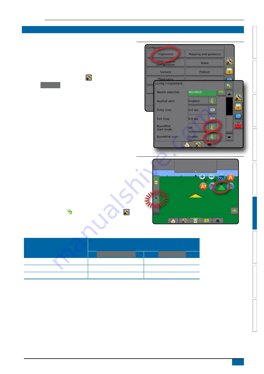
1.  Press CONFIGURATION side tab 

.

2.  Press 

 Implement 

.

3.  Select from:

►BoomPilot start mode – used to establish if automatic 

BoomPilot activation is controlled automatically by speed 

or manually using the BoomPilot icon in the navigation and 

guidance options on the guidance screens

◄Automatic – automatic section control will be controlled 

by speed

◄Off – automatic section control is disabled and can 

be manually controlled by the BoomPilot icon in the 

navigation and guidance options on the guidance 

screens

►BoomPilot icon – used to establish if the BoomPilot icon 

is available in the navigation and guidance options on the 

guidance screens for manually controlling BoomPilot

◄Enable – BoomPilot icon will be available in the 

navigation and guidance options on the guidance 

screens to control automatic section control

◄Disable – BoomPilot icon will not be available in the 

navigation and guidance options

4.  Press RETURN arrow 

 or CONFIGURATION side tab 


to return to the main Configuration screen.

Figure 6-37: BoomPilot options

Figure 6-38: BoomPilot icon on Guidance screen

0.0

km/h

0.00

ha

Mark A

Availability with different hardware systems 

Hardware on System

Available on Configuration-> Implement menu  

and works when on guidance screens

 BoomPilot start mode 

 BoomPilot icon 

SDM/SFM Only (no TeeJet ASB SwitchBox)

Yes

Yes

SDM + TeeJet ASB Switchbox

No

No

SFM + ISM

Yes

Yes

Summary of Contents for Matrix Pro 570GS

Page 1: ...VOYAGER 570G U S E R M A N U A L U S E R M A N U A L MATRIX PRO GS Software version 4 31...

Page 2: ...status information Implement setup 1 Press CONFIGURATION side tab 2 Press Implement Implement setup is used to establish the various settings associated with straight mode spreader mode or staggered...

Page 3: ...USE 3 Bottom tab keys 3 Unavailable options when job is active 3 Console screen colours 4 Simple or advanced mode 4 Warnings and information pop ups 5 Setup option information 5 Drop down menu select...

Page 4: ...19 PRN not shown 19 Video 19 Video setup unavailable 19 Sensors 20 Sensors unavailable 20 Input output module pressure sensor 20 Droplet size monitor 20 Product 21 Third party rate control 21 AutoSte...

Page 5: ...ternate PRN 39 PRN not shown 39 Show refresh GNSS position button 40 GNSS glossary 40 CHAPTER 6 IMPLEMENT SETUP 42 IMPLEMENT TYPE 42 Section numbers 42 Straight 43 Single section 43 Multiple sections...

Page 6: ...AR 63 Navigation activity boom status 63 Cross track error 63 Selectable information 63 STATUS BAR 64 Status Information Screens 64 NAVIGATION SCREENS 66 Vehicle view 66 Field View 67 RealView guidanc...

Page 7: ...POSITION 76 BOUNDARIES AND POLYGONS 77 Mapping location 77 Boundaries 77 Delete last marked boundary 79 Boundary on status bar 79 Polygons 79 Delete last marked polygon 80 MAPPING OPTIONS 81 Polygon...

Page 8: ...en mapping 88 Polygons map 89 On screen mapping 89 Prescription map 89 On screen mapping 89 Application and target rate maps 89 Application map 89 On screen mapping 89 Target rate map 90 On screen map...

Page 9: ...Sensor Interface Kit for Droplet Size Monitor Third Party Rate Control SYSTEM COMPONENTS Matrix Pro 570GS console The Matrix Pro 570GS is designed to provide years of service under typical agricultura...

Page 10: ...n Buttons Power on off On Press the POWER button to power on the console Upon power up the Matrix Pro GS will begin its start up sequence Off Press and briefly hold the POWER button until a confirmati...

Page 11: ...ode the console is in the basic screen functions are the same Bottom Tabs and Side Tabs access the various screens and sub screens Warnings and Information Pop ups inform user of console activities an...

Page 12: ...he home screen Only the current job is available for saving in Reports Use with Fieldware Link is not available Figure 1 6 Simple mode home screen In advanced mode more than one job will be available...

Page 13: ...move the information box press anywhere on the screen Figure 1 9 Example of Information Text Box Drop down menu selections Press DOWN arrow to access the options Use the UP DOWN arrows or slide bar if...

Page 14: ...enter a value Press the ACCEPT icon to save the settings or the CANCEL icon to leave the keypad without saving Figure 1 12 Example of keyboard GNSS antenna height m 1 2 3 12 5 Clear 4 5 6 7 8 9 0 Next...

Page 15: ...Only bounded area coverage areas and application time are displayed on the home screen Only the current job is available for saving in Reports Use with Fieldware Link is not available Figure 2 1 Simp...

Page 16: ...arting a new job will clear the previous job data To start a New Job 1 On the Home screen press New Job 2 Press Yes to automatically generate a name No to enter a name using the on screen keyboard Cli...

Page 17: ...ew of the video input Split camera view one of two sets of four camera inputs A B C D or E F G H can be selected to divide the screen into four separate video feeds To adjust the camera view reverse u...

Page 18: ...ealView camera full screen video view VSM camera options If a Video selection module VSM is installed on the system two 2 video options are available 1 Press REALVIEW CAMERA FULL SCREEN VIDEO VIEW bot...

Page 19: ...bar GNSS receiver configuration Video Configuration Sensors Input Output Module IOM Pressure Sensor Product configuration Third party rate control configuration AutoSteer FieldPilot Valve setup Steeri...

Page 20: ...mplement offset direction distance start stop distance section start stop offset distances In Staggered mode in line lateral section 1 offset direction distance overlap percentage delay on off times s...

Page 21: ...stances from the line availability depends on the specific equipment in the system NOTE For more information see Implement Type in the Implement chapter of this manual Figure 4 3 Implement type Straig...

Page 22: ...ly represents your machine GNSS antenna height when available used to measure the height of the antenna from the ground Implement type used to select the layout of the sections for the applied product...

Page 23: ...nd press Accept 4 Press RETURN arrow or CONFIGURATION side tab to return to the main Configuration screen Figure 4 8 Droplet size monitor Nozzle selection Nozzle selection enables up to five 5 nozzles...

Page 24: ...e versions this feature was referred to as Lightbar Mapping and guidance console only used to configure the mapping location guidance width and guidance sensitivity cross track error shown on the on s...

Page 25: ...y mode when External lightbar is enabled determines whether the lightbars represent the swath or vehicle When set to swath the LEDs represent guideline location and the moving LED represents the vehic...

Page 26: ...n in line offset direction used to select whether the mapping location is located in front of or behind the GNSS antenna as the vehicle moves in a forward direction Mapping location in line offset dis...

Page 27: ...data Set to Automatic for automatic PRN selection Alternate PRN when PRN is not automatic allows possible selection of a second SBAS PRN to provide correction data Show refresh GNSS position button es...

Page 28: ...nd set high and low user determined pressure alarms 1 Press CONFIGURATION side tab 2 Press Sensors 3 Press Input Output Module IOM Pressure Sensor 4 Select from Maximum pressure rating used to establi...

Page 29: ...vailable for configuring product control channel names and maximum minimum rate limits and corresponding display colours for mapping See the Rate Control chapter of this manual for more details Figure...

Page 30: ...n enabled select from Valve setup used to configure Valve type Valve frequency Minimum duty cycle left right and Maximum duty cycle left right Steering settings used to establish Coarse Steering Adjus...

Page 31: ...el is being turned manually Delete allows the operator to delete a vehicle profile that is no longer needed The active vehicle profile cannot be deleted Select QI values allows the user to configure t...

Page 32: ...When using a FieldPilot Pro or UniPilot Pro tilt correction is calibrated under Setup Configuration AutoSteer Manage vehicles Adjust Tilt calibration DATA MANAGEMENT Data Management allows for transfe...

Page 33: ...e as well as deleting jobs Jobs transferred to a USB storage device can be opened and updated using Fieldware Link In Fieldware Link a user can input client farm and field data as well as copy edit jo...

Page 34: ...ress RETURN arrow or DATA MANAGEMENT side tab to return to the main Data Management screen Figure 4 32 Job data manage NOTE Copying applied data is not recommended as the user will end up with two cop...

Page 35: ...d job mode Figure 4 35 Reports simple job mode Options Job mode Options allows the operator to select between Simple or Advanced job mode NOTE When a job is active started changing the job mode is not...

Page 36: ...same make and model with the same attached hardware Machine settings include Implement settings AutoSteer Tilt Correction settings Rate Control settings Job specific settings including application ra...

Page 37: ...te Machine settings used to delete machine settings from internal storage or USB storage 5 Press RETURN arrow or DATA MANAGEMENT side tab to return to the main Data Management screen Figure 4 38 Machi...

Page 38: ...ment screen Figure 4 40 Machine settings copy profile New machine settings name 1 5 9 2 6 0 3 7 4 8 q Caps Alt t f v o k Shift w a z y g b p l e s x u h n r d c i j m CONSOLE Console Setup is used to...

Page 39: ...information to the USB drive Saved version information to USB drive will confirm the save 4 Press RETURN arrow or CONSOLE side tab to return to the main Console Settings screen NOTE The Save option is...

Page 40: ...age used to define the system language Time zone used to establish the local time zone 4 Press RETURN arrow or CONSOLE side tab to return to the main Console Settings screen Figure 4 44 Cultural optio...

Page 41: ...NSOLE side tab 2 Press Demo GNSS 3 Press Restart 4 Press RETURN arrow or CONSOLE side tab to return to the main Console Settings screen Figure 4 47 Restart Demo GNSS Feature unlock Feature Unlock is u...

Page 42: ...to upload software updates from a USB drive for system devices Extras accesses Calculator and Units converter Figure 4 49 Tools options Upload software The Upload software screen is used to upload sof...

Page 43: ...oad software Extras 1 Press TOOLS side tab 2 Press Extras 3 Select from Calculator used to perform mathematical calculations Units converter used to perform unit conversions for area length volume pre...

Page 44: ...data Alternate PRN allows possible selection of a second SBAS PRN to provide correction data Show refresh GNSS position button establishes if the refresh GNSS position button is available on the guid...

Page 45: ...position data from the internal GNSS receiver these NMEA data are sent out the RS 232 serial Port A of the Matrix harness at 115 200 baud External uses position data from an externally attached GNSS r...

Page 46: ...on the receiver UTM zone zone where currently located see UTM coordinates and zones in this manual Model the correction models available to be used with the current receiver configuration 3 Press OK t...

Page 47: ...lows the user to remove SBAS correction data from malfunctioning SBAS satellites 1 Press DOWN arrow to access the list of options 2 Select Automatic automatic PRN selection Number contact your local d...

Page 48: ...across a given geographic region such as an entire state county that are networked via a centralized computer and which broadcast RTK correction data over the Internet CORS networks may be publicly or...

Page 49: ...pplication that makes the RTCM correction data from the CORS stations available to anyone with an internet connection and the appropriate log on credentials to the NTRIP server Typically uses a cellul...

Page 50: ...are on a line a fixed distance from the antenna In spreader mode a virtual line is created in line with the delivery disks from which the application section or sections can vary in length and can be...

Page 51: ...le SFM 1 Select Straight implement type on Implement screen 2 Press Implement Type NEXT PAGE arrow 3 Select from Implement in line offset direction establishes if the implement is located in front of...

Page 52: ...m Setup type used to select TeeJet spreader type Antenna to Disks Distance used to define the distance from the GNSS antenna to the disks or dispersal mechanism Implement lateral offset direction defi...

Page 53: ...om section control Delay on time used to set the time when the section will switch on when entering an area that has not been applied NOTE If the application turns on too soon when entering an unappli...

Page 54: ...RIX Pro 840GS HOME SETUP GUIDANCE FULL SCREEN INTRODUCTION GNSS RATE CONTROL APPENDIX IMPLEMENT Figure 6 12 Multiple sections Figure 6 13 Distances and length Figure 6 14 Lateral offset direction and...

Page 55: ...ion Multiple sections Section control is available SmartCable Section driver module SDM or Switch function module SFM 1 Select Spreader implement type on Implement screen 2 Press Implement type NEXT P...

Page 56: ...ine s forward direction Implement lateral offset distance defines the lateral distance from the centerline of the machine to the center of the implement in decimal meters Overlap used to define the am...

Page 57: ...UP GUIDANCE FULL SCREEN INTRODUCTION GNSS RATE CONTROL APPENDIX IMPLEMENT Figure 6 18 Multiple sections Figure 6 19 Offset directions and distances behind section 1 Figure 6 20 Offset directions and d...

Page 58: ...ple sections Section control is available when any of the following are on the system SmartCable Section driver module SDM Switch function module SFM Application width or Working width is used to ente...

Page 59: ...24 Implement lateral offset distance GNSS offset adjustment calculation To calculate a GNSS offset adjustment using the same guideline 1 Create a straight AB line 2 With assisted auto steering engaged...

Page 60: ...re the difference between the flags of pass and pass 5 Divide the measured distance in half This difference will be the offset adjustment 6 Increase or decrease the offset distance as needed dependent...

Page 61: ...vehicle icon on a navigation screen changes direction Figure 6 27 Reverse sense module Reverse on guidance screens While travelling in reverse having BoomPilot in reverse active allows for product ap...

Page 62: ...1 5 selects up to five 5 nozzles for quick recall and selected the current nozzle for determining droplet size information Current nozzle displays the current nozzle 5 Press RETURN arrow or CONFIGURAT...

Page 63: ...6 33 Current nozzle VC 3 5 bar Mark A AIXR TeeJet AIXR11004 Very coarse 0 1 2 3 4 5 6 bar 3 5 bar DROPLET SIZE MONITOR When the system includes a Pressure Sensor Interface Kit PSIK Droplet Size Monit...

Page 64: ...urrent droplet size Colour options include Crossed out Disabled No icon no Pressure Sensor Interface Kit is installed on system Droplet size chart When choosing a spray nozzle that produces droplet si...

Page 65: ...by speed Off automatic section control is disabled and can be manually controlled by the BoomPilot icon in the navigation and guidance options on the guidance screens BoomPilot icon used to establish...

Page 66: ...t rate maps can direct product application Overview Three guidance screens assist in keeping you informed Vehicle view guidance creates a computer generated image of the vehicle position displayed in...

Page 67: ...uidance options On any guidance screen displays navigation options including guidance modes guideline options return to point options refresh GNSS BoomPilot toggle curved lookahead toggle 12 deg 13 0...

Page 68: ...ck to the Marked Point BoomPilot Toggles the Automatic sprayer control ASC on or off Greyed GNSS is unavailable Curved lookahead Indicates where the current steering will take the vehicle using a poin...

Page 69: ...Pause polygon pauses the mark polygon process Resume polygon resumes the mark polygon process Delete last marked polygon deletes the last marked polygon from the current job Press again to remove addi...

Page 70: ...widest area available RealView guidance options On RealView guidance screen displays camera setup and guidance over video options 12 deg 13 0 0 Video camera select selects one of up to eight camera vi...

Page 71: ...measurement format Selectable information Speed displays the current speed of travel Heading displays the course of travel based clockwise from a true north baseline North 0 East 90 South 180 West 27...

Page 72: ...ring Status Green engaged actively steering Yellow enabled all conditions have been met to allow for assisted auto steering Red disabled all conditions have not been met to allow for assisted auto ste...

Page 73: ...formation regarding the current status of the assisted auto steering system including tilt status 1 Press ASSISTED AUTO STEERING STATUS icon 27 00 ha 10 0 km h Mark A TR 0 1 deg sec Tilt corrections d...

Page 74: ...ith real time representation of active boom sections Navigation and guidance options tab Boundary and polygon options tab Mapping options tab On screen guidance Guidelines Orange active guidance line...

Page 75: ...27 00 ha 10 0 km h 0 0 Overlap coverage area Status bar Mapping options tab Guidance bar Mapped coverage area Navigation guidelines Vehicle representation Navigation and guidance options tab Boundary...

Page 76: ...he system two 2 video options are available One camera view one of up to eight camera inputs can be selected to change the view of the video input Split camera view one of two sets of four camera inpu...

Page 77: ...e guidance Adaptive curve AB guidance Adaptive curve guidance provides guidance along a curved line based on an initial AB reference line where each adjacent guideline is drawn from the projected guid...

Page 78: ...ce mode to another will change the current available guidelines Multiple guidelines can be created in each guidance mode If more than one guideline is saved in a single guidance mode the Next Guidelin...

Page 79: ...Enter name 1 5 9 2 6 0 3 7 4 8 q Caps Alt t f v o k Shift w a z y g b p l e s x u h n r d c i j m Figure 7 12 Follow guidance 13 18 7 2 km h 0 0 A nudge feature The A Nudge feature allows the current...

Page 80: ...ss NAVIGATION AND GUIDANCE OPTIONS tab to display navigation options 2 Press NEXT GUIDELINE icon Toggle between all guidelines by pressing the NEXT GUIDELINE icon again Figure 7 14 Next guideline 13 7...

Page 81: ...e will be provided for the next adjacent row When the vehicle is in the row the guideline is removed 5 Repeat at the end of the next row NOTE The NextRow guidance feature does not support skipping row...

Page 82: ...POINT icon Figure 7 20 Return point established Vehicle view 8 19 1 7 km h 8 21 1 7 km h Delete the return point To delete the established return point 1 Press NAVIGATION AND GUIDANCE OPTIONS tab to...

Page 83: ...S tab to display navigation options 2 Press BOOMPILOT icon 3 Press BOOMPILOT icon to toggle the section on or off With optional work on off switch The work on off switch is used to turn the section on...

Page 84: ...ter as guidance The Curved lookahead option is available in all guidance modes To activate the Curved lookahead guideline 1 Press NAVIGATION AND GUIDANCE OPTIONS tab to display navigation options 2 Se...

Page 85: ...and automatic section control can then be used NOTE If a boundary is mapped with some sections folded as described above it may be necessary to use the A NUDGE icon on the guideline over to the corre...

Page 86: ...ation Continue using this location Yes Cancel 2 32 ha 7 2 km h 3 68 ha 7 2 km h 3 68 ha 7 2 km h Area bounded 64 45 ha Would you like to save the marked boundary Save Delete Figure 7 27 Add interior b...

Page 87: ...to 100 polygons can be stored within a single job Application is not required to map a polygon Using Data Job data Manage or with Fieldware Link a user can duplicate and edit jobs for reuse of polygon...

Page 88: ...to save and name the marked polygon Save without naming Save and name Discard 7 03 ha 7 2 km h Polygon name 1 5 9 2 6 0 3 7 4 8 q Caps Alt t f v o k Shift w a z y g b p l e s x u h n r d c i j m 7 03...

Page 89: ...ed map that provides information to the rate controller for use in applying product Application map shows how much product has been applied and where using colour to indicate level in proportion to pr...

Page 90: ...used to adjust the map s visible area Zoom in will decrease the amount of map area visible Zoom out will increase the amount of map area visible PAN MODE While in Field view guidance the Pan mode allo...

Page 91: ...options 3 Select from Single camera view VSM only one 1 of up to eight 8 camera inputs can be selected to change the view of the video input Split camera view VSM only one 1 of two 2 sets of four 4 c...

Page 92: ...SM camera options If a Video selection module VSM is installed on the system two 2 video options are available 1 Press REALVIEW OPTIONS tab to display RealView options 2 Select from Single camera view...

Page 93: ...gure Third party rate control settings used to configure hardware interface and communication 6 On the Matrix Pro GS console configure Product settings used to configure product name tank bin volumes...

Page 94: ...tatus used to view the status of a connected Third party rate controller Figure 8 2 Third party rate control Product When a Third party rate control system is present and Rate control has been unlocke...

Page 95: ...following selectable information will become available with Third party rate control Actual application rate displays the current application rate Target application rate displays the target applicat...

Page 96: ...Data management Job data Transfer and Data management Job data Manage in the System setup chapter for details Using Data Reports reports in multiple formats can be generated that contain data and any...

Page 97: ...port VRA jobs created in Fieldware Link as well as export job data from the console edit the included maps to create Target rate or Prescription maps and transfer back to the console for job use NOTE...

Page 98: ...ve jobs Colour range selection Product options configure maximum minimum rate limits and corresponding display colours for mapping 1 Press CONFIGURATION side tab 2 Press Product 3 Select Colour Range...

Page 99: ...UniPilot or BoomPilot kits to power cable to RS 232 Matrix Pro 570GS Matrix Pro 840GS Kit RAM Mount w Suction Cup 90 02349 Matrix 570 90 02700 Matrix 840 RXA 30 GNSS Antenna RX520 GNSS Receiver GNSS...

Page 100: ...FieldPilot Pro Vehicle Specific Steering Valve FieldPilot Pro Harness 45 05986 Ethernet Interface RJ5 to Conxall 65 05251 Bracket SCM Pro Flat 91 05023 UniPilot Pro Assy Anti Rotation Pin Kit RAM Mou...

Page 101: ...o Fieldware Link Implement Machine type GNSS antenna height Implement type Symmetric implement layout Number of implement sections Application working width Droplet size monitor Nozzle selection Curre...

Page 102: ...ode LED spacing External lightbar External lightbar LED brightness External lightbar text brightness External cross track External swath number External speed External actual rate External target rate...

Page 103: ...aggressiveness Cross track error Line acquisition Reverse response Tilt calibration Wheel angle sensor WAS calibration Select QI values Maximum DOP Transport mode Service mode Operator presence Autost...

Page 104: ...mode Machine settings Transfer Export Import Delete Manage New Copy Delete Save Load Console settings Console Settings Available with Active Job About System information Save Display Colour scheme LC...

Page 105: ...0 794 kg Matrix Pro 840GS 1 06 kg Connector Power CAN 8 pin Conxall Camera 5 pin Conxall Speed Status 8 pin Conxall WARNING Some original Matrix consoles have a 4 pin conxall cable connection The 4 p...

Page 106: ...the surface of the Earth into sixty numbered north south zones which are further divided into latitude zones designated by letters as shown below Figure A 4 UTM Coordinate System Global The Matrix Pro...

Page 107: ...ERRUPTION OF BUSINESS OR FOR INDIRECT SPECIAL INCIDENTAL OR CONSEQUENTIAL DAMAGES OF ANY KIND EVEN IF TEEJET TECHNOLOGIES HAS BEEN ADVISED OF SUCH DAMAGES ARISING FROM TEEJET TECHNOLOGIES SOFTWARE Saf...

Page 108: ...oomPilot automated section control Tilt gyro module Video selection modules for up to 8 cameras External GNSS receiver or antenna upgrades Fieldware Link enhanced data organization application Pressur...

Reviews: