


32
Chapter 3
V.
Selecting Capacitors
Never use a capacitor with a lower voltage rating
than that specified. A higher voltage rating than that
specified is acceptable.
A. Start Capacitor Bleeder Resistors
Modern high power factor, low current single phase
compressor motors which require start and run
capacitors used with potential type relays can create
electrical circuits which could cause starting relay
damage resulting in compressor failure.
The high voltage stored in the start capacitor could
discharge across the contacts of the starting relay
thus welding them and preventing the relay from
functioning. Capacitor failure and/or start winding
failure could result.
To eliminate this, Tecumseh Products Company
start capacitors are equipped with bleeder resistors
wired across the capacitor terminals. No start capac-
itor used in conjunction with a potential relay and
run capacitor should be installed without such a
bleeder resistor.
In an emergency where no bleeder resistor equipped
capacitors are available, then a two watt 15,000 ohm
resistor can be obtained and soldered across the
capacitor terminals.
B. Start Capacitor Substitution
If the specified start capacitor is not available, you
may use the next larger sized MFD capacitor at the
same or higher voltage rating. Do not add excessive
starting capacitance.
C. Run Capacitors
Since January 1979, capacitors provided by Tecum-
seh have contained non-PCB oils or have been con-
structed using non-PCB impregnated metallized
paper electrodes and polypropylene dielectric. These
capacitors are protected against case rupture, if fail-
ure occurs, by a device within the capacitor can. The
operation of this safety device could cause the termi-
nal end to bulge outward 1/2”. Suitable head space
and/or rubber caps should be provided when install-
ing such capacitors.
In some instances, for reasons of both space and eco-
nomics, it is advantageous to use two capacitors
whose MFD values add up to the total amount spec-
ified. In these cases, the capacitors should be con-
nected in parallel. Rated voltage for each should not
be less than that specified.
The tolerance on a run capacitor is ±10%, and
therefore only one rating figure is given. You should
not go below this figure on any application. You
may exceed this figure by a small amount, and the
limits are shown in this table:
Remember the voltage rating of all capacitors must
be the same or greater than the original rating. If
you do not know the voltage, use 370 volt capacitors
on 115 volt units and 440 volt capacitors on 230
volt units.
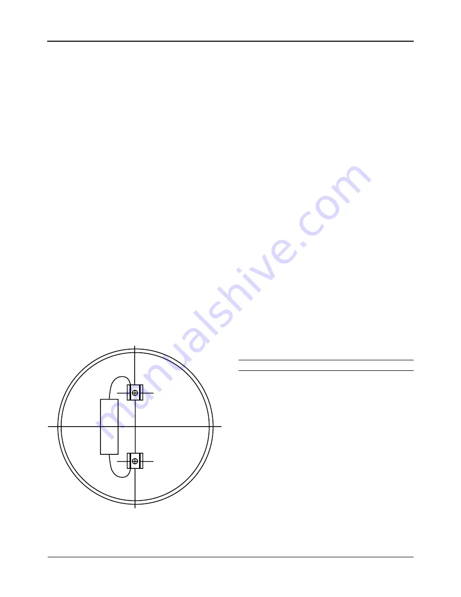
Figure 3-23.
15000 OHMS 2 WATT ± 20%
bleeder resistor wired across
capacitor terminals.
Table 3-8: Limits for Run Capacitor Ratings
Specific Rating
Maximum Addition
10 to 20 MFD
+ 2 1/2 MFD
20 to 50 MFD
+ 5 MFD
Over 50 MFD
+ 10 MFD


