1MN0046 REV. 0
operates with ISO9001 certified quality system
http: //www .tecsystem.it
R. 1.4 07/11/16
“Translations
of
the
original
instructions”
TECSYSTEM S.r.l.
20094 Corsico (MI)
Tel.: +39-024581861
Fax: +39-0248600783
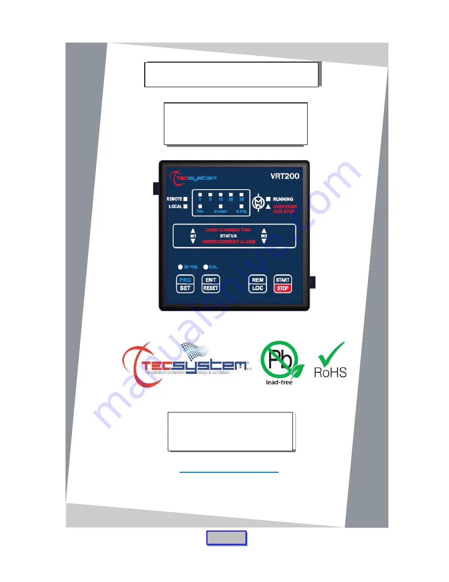
VRT200
INSTRUCTION MANUAL
ENGLISH


