


15
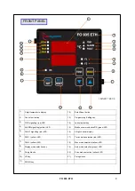
FO 935 ETH
FO 935 ETH
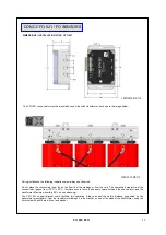
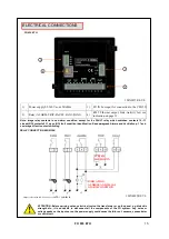
ELECTRICAL CONNECTIONS
RELAY CONNECTION EXAMPLE
1MN0095 REV.0
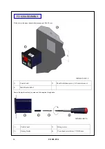
ATTENTION: Before carrying out any electrical test on the transformer or on the panel, e.g. dielectric
strength etc., it is advisable to disconnect all the components of the FO system. Any noise or
voltage peaks on the inputs or on the power supply could cause the failure of: sensors, concentrator
or control unit.
1MN0257 REV.0
1
2
3
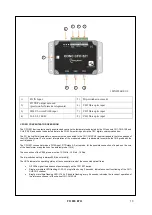
INDICATION
AUDIBLE AND VISUAL
ALARM CONDITION
SYSTEM
SHUTDOWN
Note: image relay contacts in non-alarm condition, except for the FAULT relay which switches: contacts 10
–11
closed (NO) contacts 9-11 open (NO) fault condition identification. Read paragraph Alarms and Ventilation p. 17 and
see image of fault contact switching.
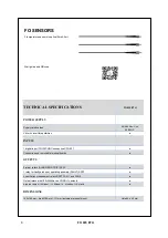
1)
Power supply 85-260Vac-dc 50/60Hz
3)
FO IN bus input for connection to the CFO 521
2)
Relay (ALARM-TRIP-FAULT-FAN1-FAN2)
4)
RJ45 Ethernet output, Link-Activity led, see
indication on page 33.
Output relays with 10A-250Vca-res COS
Ф
=1
contacts
4


