to the actuator to switch from "all opened" position to "all closed"
position.
SHrl
- MINIMUM CONTROL VALUE OF THE MOTORISED ACTUATOR
: It's the value that has to reach the control power (in %) before than
having effect on the output.
dbEr -
DEAD ZONE : It's the zone around the Set point, on which the
control output are not activated. The control output are not activated when
the process value is included into [SEt1 - dbEr ... SEt1+ dbEr].
PoSi -
POSITIONING AT START-UP OF MOTORISED ACTUATOR :
Permits to decide if, at the instrument start-up, the actuator has to remain
where it is ("no"), has to reach the maximum opening ("OPEn") or has to
reach the maximum closing position ("CloS").
Slor
- GRADIENT OF RISE RAMP : Gradient of the rise ramp to be
actuated for control when the process value is minor than the Set point,
expressed in unity/minut.
SloF
- GRADIENT OF FALL RAMP : Gradient of the fall ramp to be
actuated for control when the process value is higher than the Set point,
expressed in unity/minut.
SEnS
- INPUT PROBE : Permits to select the kind of input probe :
thermocouples B ("b"), E ("E"), J ("J"), K ("CrAl"), N ("n"), R ("r")
,
S
("S"), T ("t"), L ("L"), U ("u"), thermoresistances PT100 IEC ("Pt1"),
PT100 JIS ("Pt2") or tension signals 0...50 mV ("0_50").
ECJC -
COLD JUNCTION EXTERNAL COMPENSATION
:
Permits to
exclude ("yES") the function of cold junction compensation of the
thermocouple connected with the instrument. Otherwise ("no") the function
is active.
tCJC -
COLD JUNCTION TEMPERATURE COMPENSATION
:
If it's
programmed par. "ECJC" = "yES", set on this parameter the
compensation temperature of the cold junction.
Unit
- UNIT OF MEASUREMENT : When are used probes to determine
the temperature measure, it permits to decide if the visualisation is
expressed in Degree Centigrade ("C"), Fahrenheit ("F") or Reamur ("r").
ScaL -
RANGE OF ANALOGUE INPUT FOR NORMALISED SIGNALS :
Permits to determine the beginning scale input for normalised signals. On
this par. therefore has to be to programmed : "SSLo" if it's desired to use
the beginning of the scale = 0 (0 mA, or 0V) or "SSHi" if it's intended to
use the beginning of the scale different from 0 (4 mA, 1V or 2V)
dP -
NUMBER OF DECIMAL FIGURES : Permits to establish the
measure resolution as 1("0"), 0.1 ("1"), 0.01 ("2"), 0.001 ("3"). Pls. note
that if the input is for temperature probes the possible resolutions are 1°
and 0.1°.
StrS -
LOWER LIMIT OF ANALOGUE INPUT SCALE FOR
NORMALISED SIGNALS
:
Value that the instrument has to visualise when
on input it's present the minimum value measurable by the scale (0/4 mA,
0/1V or 0/2V).
EndS -
HIGHER LIMIT OF ANALOGUE INPUT SCALE FOR
NORMALISED SIGNALS
:
Value that the instrument has to visualise when
on input it's present the maximum value measurable by the scale (20 mA,
5V or 10V).
Aout -
ANALOGUE OUTPUTS RANGE : Permits to determine the scale
beginning of the analogue outputs. On this par. will be then programmed :
"0" if it's desired to use the beginning of the scale = 0 (0 mA, or 0V) or
"no_0" if it's intended to use the beginning of the scale different from 0 (4
mA, 1V or 2V)
OFFt
- CALIBRATION : Positive or negative Offset that is
addicted to the value measured by the probe, first than the visualisation, on
which is depending as well the functioning control.
Filt
- INPUT DIGITAL FILTER CONSTANT : Time constant of the
software filter, referred to the input value measurement, expressed in
seconds.
FrEq
-
FREQUENCY OPTIMISING THE NOISE: The instrument is
equipped with filter to limit the input noises, originated by the net. To
optimise the functioning, set then,
on this par., the net frequency on which
it's connected the instrument (50 Hz = "50H" or 60 Hz = "60H")
nStA
: ADDRESS OF THE STATION FOR SERIAL COMMUNICATION :
It's used to define the instrument address in the communication net. Set a
different number for each station, from 1 to 255.
bAud
: TRANSMISSION SPEED (BAUD-RATE) : Set the data
transmission speed (Baud-rate) of the net on which it's connected the
instrument. All the stations must have the same transmission speed.
All the stations have to be the same transmission speed.
PAcS
: PROGRAMMING ACCESS THROUGH SERIAL LINE : If
programmed as "LoCL" this means that the instrument is programmable
just from the keyboard, if programmed as "LorE" it's programmable both
from the keyboards and serial line.
nSP
-
PROGRAMMABLE SET POINT NUMBER
:
Permits to establish the
number of Set point that are desired to be programmed and memorised
(from 1 to 4).
rEar -
AUXIN INPUTS FUNCTION : Establish which kind of function
have to assume the auxiliary digital inputs : "FF" = No function, "Fr" =
Active Set point selection, "rF" = Regulator state selection, "rr" = Active
Set point selection (SP1or SP2) through AUXIN1 and instrument state
selection (regulating or Off) through AUXIN2.
rEdF
-
MANUAL CONTROL POWER WHEN ACTIVATED BY AUXIN :
Whether the digital inputs are used to establish the control state ("rEAr" =
"rF") program on this par. the control power for the manual control state.
EnOL
-
MANUAL CONTROL ACTIVATION IN "SEL" MENU : Permits to
active the possibility to switch the instrument into manual control, making
appear into "SEL" menu the option "OPLO" ("yES"). Otherwise ("no") the
"OPLO" option will be not visualised.
SPOL
-
ACTIVE SET POINT CHANGE USING "UP" KEY : If have been
memorised several Set points, it permits to select the Set point you want to
be activated, through the "UP" key ("yES"), when are happening the
control conditions. Otherwise ("no"), in control conditions, the "UP" key is
used just to visualise the control power.
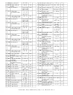
6.1 - PARAMETERS TABLES
"SEL" MENU OPTIONS TABLE
0.0
-99.9 ÷ 100.0
%
Manual control on and set control power
OPLO
-
-
Control OFF
OFF
-
-
Start Autotuning/Selftuning
tunE
1
1 ÷ 4
Active Set point
SPn
-
-
Access to configuration parameter
ConF
-
-
Access to operative parameters
OPEr
-
-
Automatic control on
rEG
Def.
Range
Description
Opt.
"OPEr" MENU PARAMETERS TABLE
0
-999 ÷ 9999
Minimum alarm A4
threshold
AL4H
17
0
-999 ÷ 9999
Minimum alarm A4
threshold
AL4L
16
0
-999 ÷ 9999
Alarm A4 threshold
AL 4
15
0
-999 ÷ 9999
Minimum alarm A3
threshold
AL3H
14
0
-999 ÷ 9999
Minimum alarm A3
threshold
AL3L
13
0
-999 ÷ 9999
Alarm A3 threshold
AL 3
12
0
0.0 ÷ 100.0
Heater Break Alarm
threshold
ALHb
11
0
-999 ÷ 9999
Minimum alarm A2
threshold
AL2H
10
0
-999 ÷ 9999
Minimum alarm A2
threshold
AL2L
9
0
-999 ÷ 9999
Alarm A2 threshold
AL 2
8
0
-999 ÷ 9999
Minimum alarm A1
threshold
AL1H
7
0
-999 ÷ 9999
Minimum alarm A1
threshold
AL1L
6
0
-999 ÷ 9999
Alarm A1 threshold
AL 1
5
0
SPLL ÷ SPHL
Set point 4
SEt4
4
0
SPLL ÷ SPHL
Set point 3
SEt3
3
0
SPLL ÷ SPHL
Set point 2
SEt2
2
0
SPLL ÷ SPHL
Set point 1
SEt1
1
Notes
Def.
Range
Description
Par.
TECNOLOGIC - THP 94
USER MANUAL (I - GB) - Vr. 05 - ISTR 01195 - PAG. 20

