background image


This document contains information considered proprietary and confidential to Tecnar Automation Ltd 

40101-00020-00– Rev 1.2 

Revision date: 2017-07-31 

Page 45 of 48 


6.18.4 

TRAVEL


SPEED: 

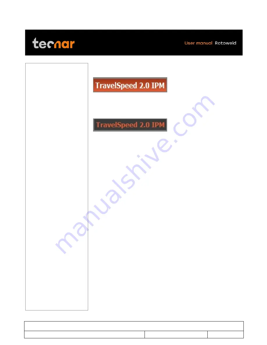
Move the joystick on the TRAVEL SPEED parameters (figure 66). 


FIGURE 61 TRAVEL SPEED 

By  pressing  the  SELECTION/ENTER  knob  you  will  be  able  to  change  the 
desired value by moving the joystick up or down (figure 67). 


FIGURE 62 TRAVEL SPEED 

Once finished, you can exit the TRAVEL SPEED parameters by pressing the 
SELECTION/ENTER knob. 


Summary of Contents for Rotoweld 3.0

Page 1: ...User manual Automated welding work cell for pipe spool prefabrication ...

Page 2: ...ed in July 2017 The material contained in this document is provided as is and is subject to change without notice in future versions or revisions OVERVIEW Table of content at the beginning of the document Table of figures at the beginning of the document Orientation a Table of contents at the front of the manual b Index at the rear of the manual This manual contains the following sections c Safety...

Page 3: ...AFETY SUMMARY 6 2 INTRODUCTION 9 3 GENERAL DESCRIPTION 10 4 OPERATION OF THE WORKSTATION 12 4 1 PREPARATION OF THE WELD 12 4 2 REMOTE PENDANT 13 5 EDITABLE PARAMETERS 22 5 1 ACCESS TO EDITING MODE 28 5 2 WELDER SECTION EDITING 29 5 3 PROCEDURES SECTION EDITING 32 5 4 PIPE SIZE EDITING 35 5 5 ROOT PROCESS EDITING 36 5 6 FILL PROCESS EDITING 42 6 CONTACT US 48 6 1 SERVICE SUPPORT 48 ...

Page 4: ... 25 FIGURE 18 SELECT COPY DELETE AND EDIT 26 FIGURE 19 WELDING LINE 27 FIGURE 20 WELDING SCREEN 28 FIGURE 21 WELDER NAME SECTION 29 FIGURE 22 POPUP MENU 29 FIGURE 23 ADD WELDER 30 FIGURE 24 NEW WELDER NAME 30 FIGURE 25 DELETE WELDER 31 FIGURE 26 PROCEDURE SECTION 32 FIGURE 27 POPUP WINDOW DISPLAYED 32 FIGURE 28 COPY PROCEDURE 33 FIGURE 29 DELETE PROCEDURE 34 FIGURE 30 PIPE SIZE SECTION 35 FIGURE 3...

Page 5: ...ILL PROCESS 42 FIGURE 53 TORCH ANGLE PARAMETERS 43 FIGURE 54 TORCH ANGLE 43 FIGURE 55 DURATION 43 FIGURE 56 DURATION 43 FIGURE 57 POWER SETTING 44 FIGURE 58 POWER SETTING 44 FIGURE 59 WIRE SPEED 44 FIGURE 60 WIRE SPEED 44 FIGURE 61 TRAVEL SPEED 45 FIGURE 62 TRAVEL SPEED 45 FIGURE 63 PRE FLOW AND POST FLOW DURATION 46 FIGURE 64 PRE FLOW AND POST FLOW DURATION 46 FIGURE 65 ENABLE 46 FIGURE 66 DISABL...

Page 6: ... fumes keep exposure as low as possible and below Threshold Limit Values TLV using local exhaust or mechanical ventilation In confined spaces or under some circumstances outdoors a respirator may be required Additional precautions are also required when welding on galvanized steel Do not weld in locations near chlorinated hydrocarbon vapors coming from degreasing cleaning or spraying operations Th...

Page 7: ...uch as leather gloves heavy shirt cuff less trousers high shoes and a cap over your hair Wear earplugs when welding out of position or in confined places Always wear safety glasses with side shields when in a welding area Connect the work cable to the work as close to the welding area as practical Work cables connected to the building framework or other locations away from the welding area increas...

Page 8: ... P l Precautions for Safe Handling of Compressed Gases in Cylinders available from the Compressed Gas Association 1235 Jefferson Davis Highway Arlington VA 22202 Turn off input power using the disconnect switch at the fuse box before working on the equipment Install equipment in accordance with the U S National Electrical Code all local codes and the manufacturer s recommendations Equipment must b...

Page 9: ...ine vision and adaptive feedback to insure full penetration of the root and therefore a defect free weld Like a welder s eyes and hands the system digitizes the full image of the weld pool as picked up by a solid state camera analyses its shape and reacts in real time on welding parameters constantly adapting to varying conditions such as changes in gap root face or temperature The system operatin...

Page 10: ...itional positioner mounted on the same rail system therefore providing two independent workstations sharing the same welding carriage This allows off line loading unloading of spools in the alternate work bay without interruption of the welding process thus maximizing arc time The welding carriage consists of a base and a column on which a control pendant a monitor with the computer in the back a ...

Page 11: ...ystem on which a turn table s idler rolls and the welding carriage are installed The root pass head is positioned and performs the root pass using the system s vision feedback algorithm with the Lincoln STT power source and the fill passes either spray MIG or SAW use the Lincoln CV400i or FLEXTEC 650 2 For the fill passes the welding head is put in position and perform the fill passes using the sp...

Page 12: ...AND DIAMETER ROOT FACE WIDTH ROOT GAP 2 to 8 std 2 to 6 HW 50 to 200 mm std 50 to 100 mm HW 3 32 to 1 8 2 3 mm 1 8 to 5 32 3 to 4 mm 10 to 24 std 8 to 24 HW 250 to 600 mm std 150 to 600 mm 3 32 to 1 8 2 3 mm 5 32 to 1 4 4 to 6 mm Misalignment high low should not exceed half the root gap length Full penetration tacks must be performed using either GMAW or GTAW to hold the two sections together The ...

Page 13: ...ical remote pendant of the Rotoweld figure 2 and its controls FIGURE 2 REMOTE PENDANT OF THE ROTOWELD On the left hand side of the pendant you will find both the power switch key of the machine Figure 3 and the key that enables or disables the welding parameters adjustment Figure 4 FIGURE 3 POWER SWITCH KEY OF THE MACHINE FIGURE 4 THE KEY THAT ENABLES OR DISABLES THE WELDING PARAMETERS ADJUSTMENT ...

Page 14: ...tion Ltd 40101 00020 00 Rev 1 2 Revision date 2017 07 31 Page 14 of 48 On the right hand side of the pendant you will find a switch Figure 5 that allows you to toggle between the master or the slave station Just underneath Figure 6 a USB port is available FIGURE 5 THE SWITCH FIGURE 6 USB PORT ...

Page 15: ... welding 3 Start Start Welding N A Engage Disengage Automatic mode N A 4 Torch Arm up down N A Arm down Up Arm down Up 5 Wire Fill Root jog wire N A N A Wire less more 6 Purge Fill Root gas purge N A N A Volt less more 7 Oscillation N A N A N A Osc less more 8 Joystick left Carriage forward Cursor left Steer left Steer left 9 Joystick right Carriage reverse Cursor right Steer right Steer right 10 ...

Page 16: ...This document contains information considered proprietary and confidential to Tecnar Automation Ltd 40101 00020 00 Rev 1 2 Revision date 2017 07 31 Page 16 of 48 FIGURE 7 REMOTE PENDANT ...

Page 17: ...dered proprietary and confidential to Tecnar Automation Ltd 40101 00020 00 Rev 1 2 Revision date 2017 07 31 Page 17 of 48 5 STARTUP Turn on the main power switch located on the back of the master positioner figure 8 FIGURE 8 MAIN POWER SWITCH ...

Page 18: ...n considered proprietary and confidential to Tecnar Automation Ltd 40101 00020 00 Rev 1 2 Revision date 2017 07 31 Page 18 of 48 Turn on the on off switch key located on the left had side of the pendant Figure 9 FIGURE 9 ON OFF SWITCH ...

Page 19: ...Calibration screen will display Figure 10 FIGURE 10 CALIBRATION SCREEN WILL DISPLAY Proceed to calibration for all axes by holding down the TORCH UP knob on the pendant Wait until the Calibration complete message appears on the screen to release the knob Figure 11 FIGURE 11 TORCH UP If one or more axis fails to calibrate refer to arm error calibration on page 19 ...

Page 20: ...te normally press the stop knob 3 times to clears the errors try again to calibrate If error occurs again you must shutdown the entire machine to clears all PLC errors Before proceeding to a complete shutdown of the Rotoweld please connect a mouse to the computer and shut down the computer properly in Microsoft Windows click on start button in the left down corner and click on shutdown and select ...

Page 21: ...nformation considered proprietary and confidential to Tecnar Automation Ltd 40101 00020 00 Rev 1 2 Revision date 2017 07 31 Page 21 of 48 When the system is idle the welding screen is displayed Figure 13 FIGURE 13 MAIN SCREEN ...

Page 22: ...s information considered proprietary and confidential to Tecnar Automation Ltd 40101 00020 00 Rev 1 2 Revision date 2017 07 31 Page 22 of 48 6 EDITABLE PARAMETERS 6 1 WELDER SELECT ADD and DELETE figure 14 FIGURE 14 WELDER ...

Page 23: ...t contains information considered proprietary and confidential to Tecnar Automation Ltd 40101 00020 00 Rev 1 2 Revision date 2017 07 31 Page 23 of 48 6 2 PROCEDURES SELECT COPY and DELETE figure 15 FIGURE 15 WELDER ...

Page 24: ...ment contains information considered proprietary and confidential to Tecnar Automation Ltd 40101 00020 00 Rev 1 2 Revision date 2017 07 31 Page 24 of 48 6 3 PIPE SIZE SELECTION SELECT figure 16 FIGURE 16 SELECT ...

Page 25: ...ormation considered proprietary and confidential to Tecnar Automation Ltd 40101 00020 00 Rev 1 2 Revision date 2017 07 31 Page 25 of 48 6 4 ROOT PROCESS SELECT COPY DELETE and EDIT figure 17 FIGURE 17 SELECT COPY DELETE AND EDIT ...

Page 26: ...ormation considered proprietary and confidential to Tecnar Automation Ltd 40101 00020 00 Rev 1 2 Revision date 2017 07 31 Page 26 of 48 6 5 FILL PROCESS SELECT COPY DELETE and EDIT figure 18 FIGURE 18 SELECT COPY DELETE AND EDIT ...

Page 27: ...ns information considered proprietary and confidential to Tecnar Automation Ltd 40101 00020 00 Rev 1 2 Revision date 2017 07 31 Page 27 of 48 6 6 WELDING LINE ENABLE DISABLE SELECT AND EDIT figure 19 FIGURE 19 WELDING LINE ...

Page 28: ...n selections by pressing ENTER The editable selection will be highlighted with orange color By using the joystick you can move across the welding screen to the desired selection figure 20 FIGURE 20 WELDING SCREEN The bottom portion of the welding screen is dedicated to the welding parameters related to the selected procedure This section is also used to edit the parameters when the key is set to i...

Page 29: ...ction you can select add or delete a welder s name Press the SELECTION ENTER push button to enter the selection mode An orange highlighted word cursor will appear on screen With the joystick move the cursor to the WELDER name section figure 21 FIGURE 21 WELDER NAME SECTION When you are on the WELDER section press SELECTION ENTER button A popup window will be displayed figure 22 FIGURE 22 POPUP MEN...

Page 30: ...ired welder s name is selected press the SELECTION ENTER button to confirm your choice If you decided to return to the welding screen without choosing a new welder s name only press the STOP button to escape and return to the welding screen To add a new welder s name move the cursor to ADD WELDER figure 23 FIGURE 23 ADD WELDER Then press the SELECTION ENTER button You will then be prompted to fill...

Page 31: ...esired location with the joystick and select the desired digit or character If you hold the joystick down or up the characters will scroll faster To delete a welder s name move the cursor over the desired welder s name Then move the cursor right and select DELETE WELDER Press the SELECTION ENTER button to delete You will see an X mark beside each welder s name that you can delete except the one th...

Page 32: ...EDITING In the Rotoweld context the set of welding parameters proper to each individual pipe size are saved in a file called a procedure figure 26 With the joystick move the cursor to the PROCEDURE section figure 26 FIGURE 26 PROCEDURE SECTION When you are in the PROCEDURE section press SELECTION ENTER button A popup window will be displayed figure 27 FIGURE 27 POPUP WINDOW DISPLAYED ...

Page 33: ...stick to the desired PROCEDURE Once the desired PROCEDURE name is selected press SELECTION ENTER button to confirm your choice If you decided to return to the welding screen without choosing a new PROCEDURE only press the STOP button to escape and return to the welding screen To create a new PROCEDURE first select an existing one to start from and move the cursor to COPY PROCEDURE figure 28 FIGURE...

Page 34: ...or to the desired location with the joystick and select the desired digit or character If you hold the joystick down or up the selection will increase the speed to achieve the desired character rapidly To delete a PROCEDURE move the cursor to the desired PROCEDURE that you want to delete Then move the cursor right and select the DELETE PROCEDURE option Press the SELECTION ENTER button to delete Yo...

Page 35: ... diameters of the same material the only welding parameter that will change is the pipe spool size In such cases without changing the procedure one can simply use the PIPE SIZE option to adjust to the new diameter To do so with the joystick move the cursor to the PIPE SIZE section figure 30 FIGURE 30 PIPE SIZE SECTION Once there press the SELECTION ENTER button Move up or down with the joystick to...

Page 36: ...SS EDITING The ROOT PROCESS screen figure 31 is used to adjust several important welding parameters You can select delete or edit ROOT PROCESS FIGURE 31 ROOT PROCESS With the joystick move the cursor to the ROOT PROCESS section figure 32 FIGURE 32 ROOT PROCESS SECTION Press the SELECTION ENTER button A popup window will be displayed figure 33 FIGURE 33 ROOT PROCESS PARAMETERS ...

Page 37: ...T PROCESS edition screen 6 12 ROOT PARAMETERS TORCH ANGLE Move the joystick on the TORCH ANGLE parameters figure 34 FIGURE 34 TORCH ANGLE PARAMETERS By pressing the SELECTION ENTER knob you will be able to change the desired value by moving the joystick up or down figure 35 FIGURE 35 TORCH ANGLE When you are finished editing the value you can exit the TORCH ANGLE parameters by pressing the SELECTI...

Page 38: ... change the desired value by moving the joystick up or down figure 35 FIGURE 37 EXIT DURATION PARAMETERS Once finished you can exit the DURATION parameters by pressing the SELECTION ENTER knob POWER SETTING Move the joystick on the POWER SETTING parameters figure 38 FIGURE 38 POWER SETTING PARAMETERS By pressing the SELECTION ENTER knob you will be able to change the desired value by moving the jo...

Page 39: ...nge the desired value by moving the joystick up or down figure 41 FIGURE 41 WIRE SPEED Once finished you can exit the WIRE SPEED parameters by pressing the SELECTION ENTER knob 6 13 3 TRAVEL SPEED Move the joystick on the TRAVEL SPEED parameters figure 42 FIGURE 42 TRAVEL SPEED PARAMETERS By pressing the SELECTION ENTER knob you will be able to change the desired value by moving the joystick up or...

Page 40: ...DURATION parameters figure 44 FIGURE 44 DURATION PARAMETERS By pressing the SELECTION ENTER knob you will be able to change the desired value by moving the joystick up or down figure 45 FIGURE 45 DURATION Once finished you can exit the DURATION parameters by pressing the SELECTION ENTER knob You can also disable or enable the PRE FLOW by selected the LED image Enable figure 46 FIGURE 46 ENABLE Dis...

Page 41: ...LANEOUS 6 15 1 TRAVEL SPEED MIN MAX Move the joystick on the TRAVEL SPEED parameters figure 53 FIGURE 48 TRAVEL SPEED MIN MAX By pressing the SELECTION ENTER knob you will be able to change the desired value by moving the joystick up or down figure 54 FIGURE 49 TRAVEL SPEED MIN MAX Once finished you can exit the TRAVEL SPEED parameters by pressing the SELECTION ENTER knob ...

Page 42: ...use for multiples parameters You can select delete or edit FILL PROCESS FIGURE 50 FILL PROCESS With the joystick move the cursor to the FILL PROCESS section figure 56 FIGURE 51 FILL PROCESS SECTION When you are on the FILL PROCESS section press SELECTION ENTER button A popup window will be displayed figure 33 FIGURE 52 SELECT THE DESIRED FILL PROCESS Several parameters can be edited in the FILL PR...

Page 43: ...ELECTION ENTER knob you will be able to change the desired value by moving the joystick up or down figure 59 FIGURE 54 TORCH ANGLE Once finished you can exit the TORCH ANGLE parameters by pressing the SELECTION ENTER knob 6 18 BURNBACK SETTINGS 6 18 1 DURATION Move the joystick on the DURATION parameters figure 60 FIGURE 55 DURATION By pressing the SELECTION ENTER knob you will be able to change t...

Page 44: ... to change the desired value by moving the joystick up or down figure 63 FIGURE 58 POWER SETTING Once finished you can exit the POWER SETTING parameters by pressing the SELECTION ENTER knob 6 18 3 WIRE SPEED Move the joystick on the WIRE SPEED parameters figure 64 FIGURE 59 WIRE SPEED By pressing the SELECTION ENTER knob you will be able to change the desired value by moving the joystick up or dow...

Page 45: ...e 45 of 48 6 18 4 TRAVEL SPEED Move the joystick on the TRAVEL SPEED parameters figure 66 FIGURE 61 TRAVEL SPEED By pressing the SELECTION ENTER knob you will be able to change the desired value by moving the joystick up or down figure 67 FIGURE 62 TRAVEL SPEED Once finished you can exit the TRAVEL SPEED parameters by pressing the SELECTION ENTER knob ...

Page 46: ...rs figure 68 FIGURE 63 PRE FLOW AND POST FLOW DURATION By pressing the SELECTION ENTER knob you will be able to change the desired value by moving the joystick up or down figure 69 FIGURE 64 PRE FLOW AND POST FLOW DURATION Once finished you can exit the DURATION parameters by pressing the SELECTION ENTER knob You can also disable or enable the PRE FLOW by selected the LED image Enable figure 46 FI...

Page 47: ... 6 20 1 TRAVEL SPEED MIN MAX Move the joystick on the TRAVEL SPEED parameters figure 53 FIGURE 67 MISCELLANEOUS TRAVEL SPEDD MIN MAX By pressing the SELECTION ENTER knob you will be able to change the desired value by moving the joystick up or down figure 54 FIGURE 68 TRAVAEL SPEES MIN MAX Once finished you can exit the TRAVEL SPEED parameters by pressing the SELECTION ENTER knob ...

Page 48: ... Revision date 2017 07 31 Page 48 of 48 7 CONTACT US 7 1 SERVICE SUPPORT Below are the points of contact for questions and or service support on Rotoweld systems TECNAR Automation Ltee The original manufacturer 1321 Hocquart Street St Bruno Qc Canada J3V 6B5 Phone 1 450 461 1221 Fax 1 450 461 0808 Email service tecnar com ...

Reviews: