


tecn@
WELDERS ITEM 8201N ÷ 8214N
EDITION: MAY 2008 PAGE 15 OF 32
4.2 ELECTRODE FORCE ADJUSTMENT
The following paragraphs show how to adjust both the standard pneumatic circuit, and the
optional one with a low force squeeze. The welding force must be selected taking into
consideration both tables and personal experience, and in relation to the sheets thickness, the
desired spot quality, etc.
Always adjust by keeping the welding control unit on “NO WELD” in order to avoid
any risk caused by a wrong adjustment. Always carry out “NO WELD” cycle tests
before starting the welding process.
An excessive electrodes force can cause:
•
welding over marks;
•
possible electrodes short life;
•
weak welding or false welding due to a reduction of contact resistance, which allows the
current to pass through without bringing the piece to the melting temperature.
An insufficient force on electrodes can cause:
•
spatter of melted material;
•
stuck weld of the pieces on the electrode;
•
welding with a disagreeable outside surface.
If the welding to be carried out requires low or precise force values, it is advisable to use a
dynamometer.
4.2.1 STANDARD PNEUMATIC CIRCUIT ADJUSTMENT
The electrodes force adjustment is carried out by means of the pressure control REG1. This
carries out the pressure P1 adjustment, (displayed by pressure gauge MAN1), modifying the
welding force.
Upon demand, it is possible to have a proportional valve EVP to adjust the working pressure
directly from the control unit and to combine a proper pressure value to each program. Assures
constant and accurate working pressure.
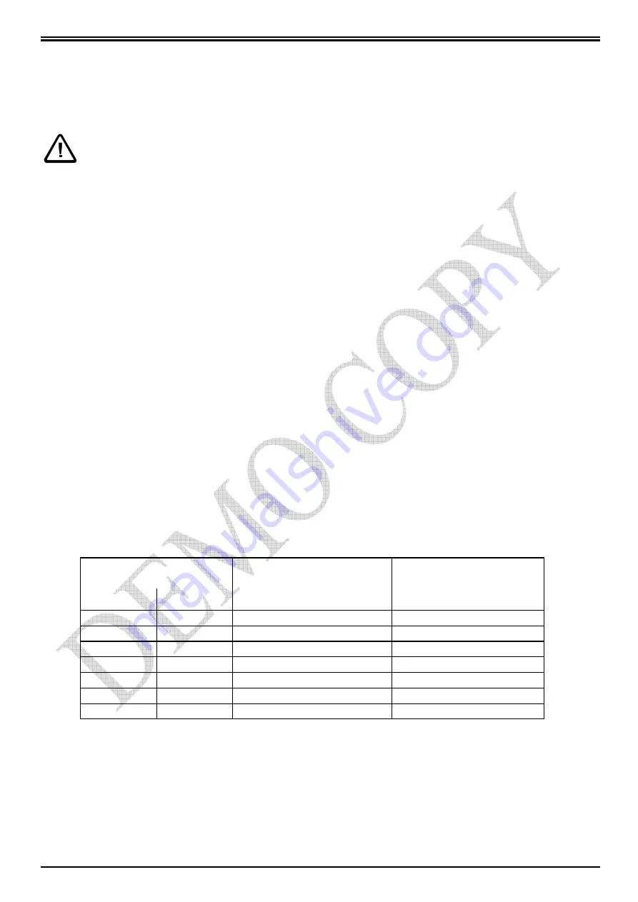
The reached force values, concerning the different pressure values showed on the pressure
gauge, are listed in the following table:
PRESSURE
CYLINDER
∅
125
(STANDARD)
CYLINDER
∅
125
×
2
(OPTION 8235)
bar
kPa
FORCE in daN
FORCE in daN
0,5
50
61
103
1
100
122
207
2
200
245
414
3
300
368
621
4
400
490
828
5
500
613
1035
6
600
736
1242
The head descent speed adjustment is carried out by means of the flow regulator RFL2; the rise
speed adjustment is carried out by means of the flow regulator RFL1. The flow regulator RFL3
must be used in order to carry out the double stroke descent speed adjustment.


