


tecn@
WELDERS ITEM 8201N ÷ 8214N
EDITION: MAY 2008 PAGE 13 OF 32
4.1 MECHANICAL SET UP
Spot welding electrodes adjustment.
With control unit set to NO WELD, the start device is activated; with the electrodes touching,
contact between electrodes should be uniform. If required, carry out the adjustment. It is
advisable to adjust electrodes with a fine file or with sandpaper. In case of steel welding, the
electrodes diameter should correspond to the values shown on the following table.
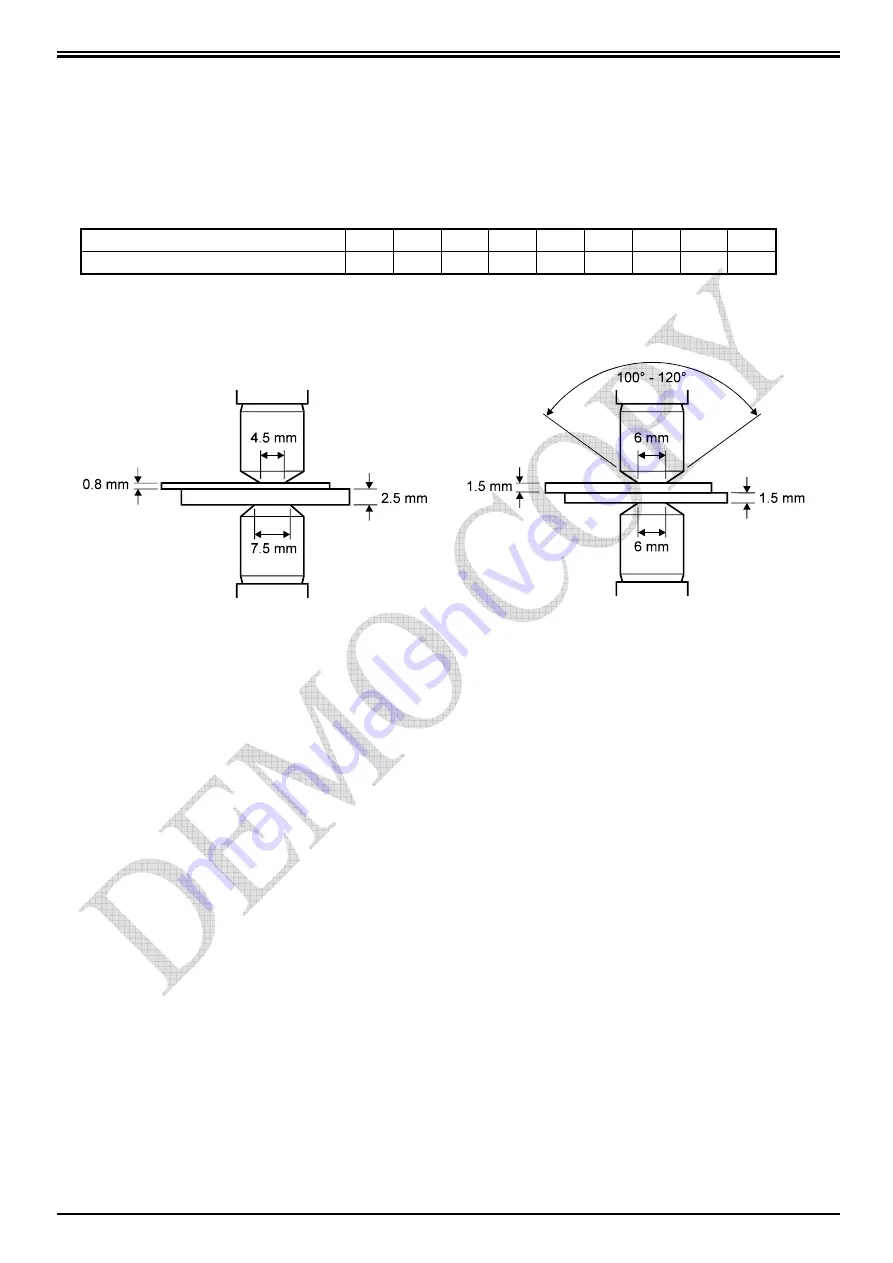
Sheet thickness
mm
0,5
0,8
1
1,5
2
2,5
3
3,5
4
Required diameter
mm
4
4,5
5
6
7
7,5
8,5
9,5
11
Suggested electrode tip angle is 120 degrees. If the thickness of the two plates is different the
electrode must have the diameter corresponding to the one required by the plate to which it gets
in touch.
A too small diameter in comparison with the thickness to be welded produces spatter of melted
material, sheets over mark, low spot quality. If the electrode diameter is too large, longer welding
times are necessary, causing a higher heating of the welder and a shorter life of electrodes. For
aluminium spot welding we suggest to use spherical electrodes, radius value varies according to
the thickness to be welded and the kind of quality required.
Projection welding tools adjustments.
When assembling the tools on the projection plates, carefully follow the herewith stated
instructions:
•
Adjust the components in order to have them perfectly combine. To facilitate this operation, on
the welding cylinder left side there is a hand-operated valve which enables the head descent
by discharging the back pressure.
•
Welding force must be equally distributed on the different welding spots; for this reason, tools
must be parallel when the desired welding force is applied to them.
•
Adjust stroke to the minimum value to increase the tool follow up.


