TechVision PDVR-S4L15 Manual Download Page 111

Device Management 


DVR  User  Manual


103 


the tool bar at the bottom of the live view interface to view network status conveniently. 
 

11.2    Basic Configuration 

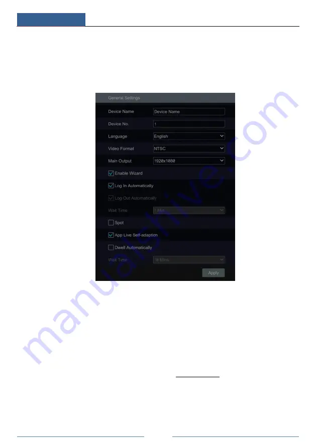
11.2.1    Common Configuration 

Click Start

Settings

System

Basic

General Settings to go to the following interface.   


Set the device name, device No., language, video format and main output resolution. Enable or 
disable wizard, “Log In Automatically”, “Log Out Automatically” (if checked, you can set the 
wait time) “App Live Self-Adaption” and “Dwell Automatically” (if checked, you can set the 
wait time). Click “Apply” to save the settings. 
 

Device Name

: The name of the device. It may display on the client end or CMS that help user 

to recognize the device remotely.


Video Format

: Two modes: PAL and NTSC. Select the video format according to the camera. 

Spot

If  the  DVR  supports  spot  output,  you  can  enable  spot  output.  Connect  the  spot  output 

device to the DVR and then set the spot output (see 5.2.4 Spot View for details).     

Dwell  Automatically:

  Switch  automatically.  Check  it  and  set  “wait  time”.The  system  will 

switch images automatically if it is not operated during the time you set. 
 

11.2.2    Date and Time Configuration 

Click Start

Settings

System

Basic

Date and Time to go to the interface as shown below.   

Summary of Contents for PDVR-S4L15

Page 1: ...1080P 4 Channel NVR PDVR S4L15...

Page 2: ...company names products that are not owned by our company are the properties of their respective owners It is recommended to back up and clear the personal data stored in the device before the device i...

Page 3: ...t some important ports cannot be closed like HTTP port HTTPS port Data Port It is not recommended to expose the device to the public network When it is necessary to be exposed to the public network pl...

Page 4: ...accordance with Directive EU RoHS Directive 2011 65 EU and its amendment Directive EU 2015 863 on the restriction of the use of certain hazardous substances in electrical and electronic equipment 2012...

Page 5: ...Main Interface 18 3 2 1 Main Interface Introduction 18 3 2 2 Setup Panel 20 3 2 3 Main Functions 22 4 Camera Management 23 4 1 Camera Signal 23 4 2 Add Edit Camera 23 4 2 1 Add Camera 23 4 2 2 Edit Ca...

Page 6: ...ion 56 8 Playback Backup 57 8 1 Instant Playback 57 8 2 Playback Interface Introduction 57 8 3 Smart Playback 60 8 4 Record Search Playback Backup 62 8 4 1 Search Playback Backup by Time sliced Image...

Page 7: ...etwork Configuration 90 11 1 1 TCP IP Configuration 90 11 1 2 Port Configuration 91 11 1 3 PPPoE Configuration 92 11 1 4 DDNS Configuration 93 11 1 5 E mail Configuration 95 11 1 6 UPnP Configuration...

Page 8: ...Preview 111 12 4 2 Remote Playback 114 12 4 3 Remote Backup 115 12 4 4 Remote Configuration 115 Appendix A FAQ 116 Appendix B Calculate Recording Capacity 121 Appendix C Compatible Device List 122 Ap...

Page 9: ...ters mask motion and so on Support multiple ser permission groups including Administrator Advanced and Ordinary which are the default permission groups of the system Support multiple users to be creat...

Page 10: ...recording and motion detection recording etc Support schedule recording and event recording setting with different record streams Support record schedule setting and recycle recording Support pre rec...

Page 11: ...ievement configuration import and export of the DVR parameters and other system maintenance operations including remote upgrading and system restart Support remote camera configuration of the DVR incl...

Page 12: ...rding the light is blue Net When access to network the light is blue Power Power indicator when the device is powered the light is blue Fn No function temporarily Type II Name Descriptions Power Power...

Page 13: ...for references Please take the real object as the standard No Name Descriptions 1 AUDIO IN Audio input 2 ALARM IN Alarm inputs for connecting sensors 3 ALARM OUT Relay output connect to external alarm...

Page 14: ...output connect to sound box 5 AUDIO IN Audio input 6 ALARM OUT Relay output connect to external alarms 7 VIDEO IN 8 CH video inputs 8 HDMI Connect to high definition display devices 9 VGA Connect to...

Page 15: ...monitor 9 USB Connect USB storage devices or USB mouse 10 DC12V DC12V power input 1 5 Connections Video Connections Video Output Supports VGA HDMI video output You can connect to monitor through these...

Page 16: ...If the input is not an open closed relay please refer to the following connection diagram Alarm Output The way to connect alarm output device Pull out the green terminal blocks and loosen the screws i...

Page 17: ...port separately Y is TX Z is TX and tighten the fixed screws Next connect pluggable block back into terminal block Finally connect the video cable of the speed dome to the video input interface of th...

Page 18: ...y clicking OK button Disconnect the power By mouse Click Start Shutdown to pop up the Shutdown window Select Shutdown in the window and click OK button The unit will power off after a while after veri...

Page 19: ...eset setting in PTZ mode Cruise Button To go to cruise setting in PTZ mode Track Button No track function temporarily Wiper Button No function temporarily Light Button No function temporarily Clear Bu...

Page 20: ...nel and the panel will disappear automatically after you move the mouse away from it Mouse control in text input Move the mouse to the text input box and then click the box The input keyboard will pop...

Page 21: ...n below Button Meaning Button Meaning Backspace key Switch key of punctuation character Delete Key Enter key Switch key between upper and lower letter Space key Switch key of language 2 5 Common Butto...

Page 22: ...language and locality as needed if it is the first time for you to use the wizard and then read the privacy statement Date and Time Configuration The date and time of the system need to be set up if y...

Page 23: ...erial number R W status of the disk Click Format to format the disk Click Next to continue Then click Wizard Setup Network Settings Check Obtain an IP address automatically and Obtain DNS automaticall...

Page 24: ...o edit the searched IP camera as shown on the below left Enter the new IP address subnet mask gateway and the password of the camera Click OK to save the settings Click to edit the added camera as sho...

Page 25: ...RAID0 RAID1 RAID5 RAID6 and RAID10 The global hot spares and array capacity can also be viewed here See 7 4 Disk for details Click Next to continue Record Settings Two record modes are available auto...

Page 26: ...mobile client which is installed in the mobile phone or tablet to log in the mobile client instantly Please refer to 12 1 Mobile Client Surveillance for details Click OK to save the settings Cloud Up...

Page 27: ...erations 8 2 Playback Interface Introduction click to go to the playback interface For instance if you choose 5 minutes ago as the default playback time you can playback the record from the past five...

Page 28: ...e display mode in the list to switch to the display mode for previewing Introduction of area Icon Button Meaning It shows the current login user Click it to go to record search interface see 8 4 Recor...

Page 29: ...to the camera management interface as shown below There are some function items on the left side of the camera management interface Click each item to go to corresponding interface or window For inst...

Page 30: ...t for details Alarm The module covers the functions such as Sensor and Motion Alarm Handling and Alarm Out Settings Please see Chapter 9 Alarm Management for details Network The module covers the func...

Page 31: ...the camera image normally if you select AHD then there will be no image or the image has no color The default selection of the camera signal is Auto If you select Auto the image of the camera will be...

Page 32: ...r Manual 24 Quickly Add Check the cameras and then click Add to add cameras Click to edit the camera s IP address username and password and so on Click Default Password to set the default username and...

Page 33: ...iew the live image of the camera in the popup window Click to edit the camera see Add camera in 3 1 Startup Wizard for details Click to delete the IP camera Click in the Operation header line and then...

Page 34: ...cord blue stands for schedule record and cyan stands for intelligence record Click the preview window to show the tool bar as shown in area right click the preview window to show the menu list The too...

Page 35: ...ce is as shown below Press and drag the blue box to select the zoom in area Click to zoom the image Click the camera selection box to select other cameras for amplification Click Back to return to the...

Page 36: ...een mode Double click the camera or camera group in the list to add them to the selected window Click to save the current display mode refer to 5 2 3 Scheme View In Sequence for detail configurations...

Page 37: ...ble click again to restore the view Click to stop the view 5 2 3 Scheme View In Sequence Click Start Settings System Basic Output Settings Main Output to go to the interface as shown below Area displa...

Page 38: ...save the settings Start Sequence View Go to live view interface and then click to pop up a window Set the dwell time in the window and then click to start scheme view in sequence Double click the seq...

Page 39: ...ngs to go to the following interface Enter the IP address of the POS you want to add Check Filter destination Filter POS port and Filter destination Port If you do not check them please skip this step...

Page 40: ...figure under it to bind POS to the camera One POS can be bound to multiple channels but one channel can only be bound to one POS Click Apply to save the settings and then the trade information will be...

Page 41: ...to the interface as shown below Select the camera enter the camera name or double click the camera name in the camera list to change the camera name enable or disable the name and time OSDs if enabled...

Page 42: ...up Image Adjust interface and then set the relevant setting items Please refer to 5 4 5 Image Adjustment for detailed introductions of these items You can click Default button to restore the image se...

Page 43: ...button to delete the mask areas click Apply to save the settings 5 4 4 Water Mark Settings Click Start Settings Camera Image Water Mark Settings to go to the interface as shown below Select the camer...

Page 44: ...ree of color purity The color is purer the image is brighter Hue It refers to the total color degree of the image Sharpen It refers to the resolution level of the image plane and the sharpness level o...

Page 45: ...ttons are as follows Button Parameter Meaning Click to zoom in out the image Focus Mode If manual mode is selected focus button One Key Focus Day night mode switch autofocus will be available if auto...

Page 46: ...s to the camera on the top right of the interface for PTZ control Introductions of the buttons on the bottom right of the interface Button Meaning Click to rotate the dome Click to stop rotating the d...

Page 47: ...ter the dome or PTZ rotates The dome or PTZ will stop rotating when you stop dragging the analog joystick 3D Control Click the camera image on any area and then the image will be centered on the click...

Page 48: ...se to the camera image and then slide the scroll wheel of the mouse forward to zoom in the image slide the scroll wheel of the mouse backward to zoom out the image OSD Setting Go to PTZ protocol setti...

Page 49: ...e the settings You can add 255 presets for each dome at most Adjust the dome s direction and then click Save Position to save the current preset position you can also click another preset in the prese...

Page 50: ...d Cruise window you can click to reselect the preset then change the preset time and speed Click to delete the preset Click Add button to save the cruise Click to start the cruise and click to stop th...

Page 51: ...nd then click to save the new preset name Adjust the rotating speed position zoom focus and iris of the preset and then click Save Position to save the preset Delete Preset Select camera and preset an...

Page 52: ...cruise to delete the cruise 6 4 PTZ Protocol Setting Click Start Settings Camera PTZ Protocol to go to the interface as shown below You can enable or disable the PTZ and set the protocol baud rate an...

Page 53: ...larm record will be enabled when sensor alarm happens Motion Record Sensor Record Motion sensor alarm record will be enabled when motion sensor alarm happens Always 24 7 Record Motion Record Normal re...

Page 54: ...then click Add button to show the modes in the record mode list in the window the checked modes can be shown in the record mode list while the unchecked modes cannot you cannot only check Always 24 7...

Page 55: ...2 Encode Parameters Setting and 7 3 Schedule Setting for details 7 1 2 Advanced Configuration Click Start Settings Record Advanced to go to the following interface Enable or disable cycle record cycl...

Page 56: ...e by one or set them in bulk for all cameras Click Start Settings Record Stream Settings to go to Sub Stream interface Set the encode resolution FPS bitrate type quality and max bitrate of sub stream...

Page 57: ...le information on the left side of the interface The seven rows stand for the seven days in a week and each row stands for 24 hours in a day Blue stands for the selected time and gray stands for unsel...

Page 58: ...ndow and then click OK to save the settings Click All to set all day recording click Reverse to swap the selected and unselected time in a day click Clear All to clear all the selected area in a day C...

Page 59: ...n the tool bar at the bottom of the live view interface to enable recording of the camera Method Two Go to live view interface and then click the right click menu Manually Record On in the camera wind...

Page 60: ...exception line crossing or intrusion detection and draw alert surface or warning area of each IP camera See 9 3 Intelligence Alarm for details The camera will start intelligence recording once you fin...

Page 61: ...Disk Management If you don t have one you can use the user name and password that you login system the default username admin c Enter array name and select array type like RAID5 d Select physical dis...

Page 62: ...n the following pictures RAID Rebuilding If one of your disks is broken the disk indicator on the front panel will turn red Of course a warning tip will pop up if the relevant HDD exception alarm is s...

Page 63: ...atically The disks and cameras in the groups can be deleted except group one select a disk group and then click on the top right corner of the added disk or camera to delete it from the group The dele...

Page 64: ...d click Format Now to select the backup disk The added backup disk will be formatted and this disk will be removed from the normal group Then add cameras to the backup group These cameras can be added...

Page 65: ...ure below Drag the playback progress bar to change the playback time You can also click the right click menu Instant Playback in the camera window and then set the instant playback time to play back t...

Page 66: ...Start button Click it to pop up area Full screen button Click it to show full screen click it again to exit the full screen Screen mode button OSD ON button Click it to enable OSD click it again to di...

Page 67: ...n this quadrilateral after drawing it Smart playback settings Click it to set smart playback Introduction of area Button Meaning Click it to go to record search interface see 8 4 Record Search Playbac...

Page 68: ...click to recover the timeline to 24 hours ratio Drag the timeline or slide the scroll wheel of the mouse on the time scale to show the hidden time on the top or bottom of the timeline You can also cl...

Page 69: ...locks indicate that there are intelligent recording files Move the cursor to such block and click to play the record Smart Playback by Drawing Line Click and draw a line in the desired area Then the s...

Page 70: ...ere are intelligent recording files Move the cursor to such block and click to play the record 8 4 Record Search Playback Backup The record data and the snapped pictures can be backed up through netwo...

Page 71: ...mode will be disabled and the camera view mode will be available only Select one camera in the interface and then click the Open button Click the image box to play the record in the small playback box...

Page 72: ...ows and click Hour to select Hour mode Method Two Click beside Camera Thumbnail on the left top corner of the interface to select the time slice mode Method Three Right click the mouse on any area of...

Page 73: ...e to add playback camera Click Modify on the top right corner of the camera window to change the camera and click Clear to remove the camera Click the camera window to play the record in the small pla...

Page 74: ...wn below Check the event type in the interface as required Click to set the start time and end time on the top left of the interface Check cameras on the left side of the interface or check All to sel...

Page 75: ...back time point of the selected camera Click Start Search and Backup Tag Management to go to Tag Management tab Click in the interface to play the record Click to edit the tag name Click to delete the...

Page 76: ...Playback Backup DVR User Manual 68 8 4 7 View Backup Status Click Start Search and Backup Backup Status or click on the tool bar at the bottom of the playback interface to view the backup status...

Page 77: ...camera in 10 seconds If there is another motion detected during this period it will be considered as a continuous movement otherwise it will be considered as a single motion Record check it and then...

Page 78: ...m is triggered To set the duration time of the message box please see 9 5 3 Display for details E mail if enabled the system will send an e mail when the sensor alarm is triggered Before you enable th...

Page 79: ...ly to save the settings Click Processing Mode to go to the alarm handling configuration interface of the motion alarm 9 2 2 Motion Alarm Handling Configuration Click Start Settings Alarm Motion Alarm...

Page 80: ...alarm area of the object detection Refer to the interface as shown above Check Draw Area and then click around the area where you want to set as the alarm area in the image the alarm area should be a...

Page 81: ...gent Detection Exception to go to the following interface Select the camera and enable the relevant detection as needed Scene Change Alarms will be triggered if the scene of the monitor video has chan...

Page 82: ...figuration interface 9 3 3 Tripwire Tripwire Line Crossing Configuration Alarms will be triggered if someone or something crosses the pre defined alarm line Click Start Settings Camera Intelligent Det...

Page 83: ...ossing Alarm Handling Configuration Click Start Settings Alarm Intelligence Alarm Line Crossing to go to the following interface Enable or disable Record Snapshot Push Alarm out Preset Buzzer Pop up V...

Page 84: ...as the alarm area in the image the alarm area should be a closed area Uncheck the Draw Area if you finish the drawing Click the Clear button to delete the alarm area Click Apply to save the settings...

Page 85: ...he settings You can click Intrusion Config to go to the intrusion detection configuration interface 9 4 Exception Alarm 9 4 1 IPC Offline Settings Click Start Settings Alarm Exception IPC Offline Sett...

Page 86: ...Video Loss Settings are similar to that of the sensor alarm see 9 1 Sensor Alarm for details Click Apply to save the settings 9 4 3 Exception Handling Settings Click Start Settings Alarm Exception Ex...

Page 87: ...etails Click Apply to save the settings You can click Test to test the alarm output 9 5 2 E mail Click Start Settings Alarm Event Notification E mail to go to the e mail configuration interface Set th...

Page 88: ...o go to the interface as shown below Check Enable choose the push schedule and then click the Apply button to save the settings If Push Server is online it will push messages to the mobile clients 9 5...

Page 89: ...tool bar at the bottom of the live view interface to pop up a window Click Trigger to start alarm Click Clear to stop alarm 9 7 View Alarm Status Click Start Settings Alarm Alarm Status or click on t...

Page 90: ...If the exception information is more than one page you can enter the number in the box and then click to jump to the specified page Click to view the exception alarm information in the previous next...

Page 91: ...strator Advanced and Common available when adding accounts You can manually add new permission group see 10 3 1 Add Permission Group for details Only admin and the users that have the Account and Auth...

Page 92: ...ount and Authority Account Edit User and then click in the user list or double click the user to edit the user information Click to delete the user the user admin cannot be deleted Edit Security Quest...

Page 93: ...t pattern lock Recover Password Click Recover Password to reset the password to 123456 Edit User Click Edit User to pop up the window as shown below The admin is enabled its permission control is clos...

Page 94: ...rd in the popup window Click the Login button to log in the system Logout Click Start Logout or click Start Shutdown to pop up the Shutdown window Select Logout in the window and then click OK to log...

Page 95: ...then click in the group list to edit the permission group the operations of the Edit Permission Group are similar to that of the Add Permission Group please see 10 3 1 Add Permission Group for detail...

Page 96: ...P IP segment MAC you add be effective Enter the IP IP segment MAC and then click OK In the above interface click to edit IP IP segment MAC click to delete it Click Apply to save the settings 10 5 Prev...

Page 97: ...ration time of the password Level 4 levels weak medium strong stronger Expiration Time 4 options Never expire 30 days 90 days or 180 10 7 View Online User Click Start Settings Account and Authority Us...

Page 98: ...ern as required Network Fault Tolerance The two network ports will be bound to one IP address if you select the Network Fault Tolerance pattern There are many advantages of this work pattern 1 increas...

Page 99: ...lick Apply to save the settings HTTP Port the default HTTP port of the DVR is 80 The port number can be changed to others like 81 The port is mainly used to client remote access If you want to access...

Page 100: ...the camera can be accessed by entering https IP https port via the web browser eg https 192 168 1 201 443 Server Port the default server port of the DVR is 6036 The server port number can be changed...

Page 101: ...select the DDNS type Enter the server address domain name username and password according to the selected DDNS type Click Test to test the effectiveness of the input information Click Apply to save t...

Page 102: ...ser Manual 94 Click Registration to go to the interface as shown below Set the DDNS account information username password and so on and then click Submit to save the account Create domain name and the...

Page 103: ...dvrdydns com DDNS type Enter the registered username password and domain name and then click Apply Map the IP address and HTTP port in the router you can skip this step if UPnP function is enabled En...

Page 104: ...d then click the OK button The e mail address of the sender will send an e mail to the recipient If the e mail is sent successfully it indicates that the e mail address of the sender is configured cor...

Page 105: ...click Apply Click Refresh to refresh the UPnP status If the UPnP status were still Invalid UPnP after refreshing it for many times the port number would be wrong Please change the mapping type to Man...

Page 106: ...he IEEE 802 1X user authentication is needed To use this function the DVR shall be connected to a switch supporting 802 1x protocol The switch can be considered as an authentication system to identify...

Page 107: ...follows Click Start Settings Network Platform Access to go to the interface Platform Access Set Access Type as Platform Software and select Enable as shown below Check the IP address and port of the...

Page 108: ...ettings Enable 3G 4G function Choose the 3G 4G type as needed Click Network Status to view the 3G 4G connection status and get the IP address 11 1 12 Wi Fi Optional Plug in the USB Wi Fi search device...

Page 109: ...d then click Connect Enter the key password in the Wi Fi connection box and then click Connect The connection status will be displayed after the Wi Fi is connected Exit the Wi Fi connection interface...

Page 110: ...Apply to save the settings Trap Address The IP address of SNMP host Trap Port The port of SNMP host Tips Before setting the SNMP please download the SNMP software and manage to receive the device inf...

Page 111: ...u can set the wait time Click Apply to save the settings Device Name The name of the device It may display on the client end or CMS that help user to recognize the device remotely Video Format Two mod...

Page 112: ...ings to go to the following interface OSD name and icon can be enabled here 11 3 Factory Default Click Start Settings System Maintenance Factory Default and then click the Reset to factory default but...

Page 113: ...r software version is not the latest click Upgrade to download and upgrade from the cloud server Please don t power off during the upgrade process 11 5 Backup and Restore You can back up the configura...

Page 114: ...d point of time and then click Apply to save the settings The DVR will restart automatically at the pointed time every interval days 11 7 View Log Click Start Settings System Maintenance View Log to g...

Page 115: ...ecked log contents only Click to play the video log 11 8 View System Information Click Start Settings System Information and then click the corresponding menu to view the Basic Camera Status Alarm Sta...

Page 116: ...e QRCode of the DVR After scanning the QRCode successfully enter the login password to log in mobile client 12 2 Web LAN Access Click Start Settings Network TCP IP to go to the TCP IP interface Set th...

Page 117: ...n according to the popup tip if you access the DVR through NAT for the first time Notes 1 Please make sure that the IP address of the DVR and the computer are both in the same local network segment Fo...

Page 118: ...f the UPnP function is not available in the router you need to forward the LAN IP address HTTP port and server port of the DVR to the router Port mapping settings may be different in different routers...

Page 119: ...Browse to set the snapshot path and record path as shown below Click the Apply button to save the settings 12 4 1 Remote Preview Click Live Display in the remote interface to go to the preview interf...

Page 120: ...le OSD Click it to show full screen Right click on the full screen to exit full screen Click All Main Stream or All Sub Stream to set the stream of all the cameras Manual alarm button Click it to pop...

Page 121: ...ick it to snap Click it to start record to computer Click it to start record to the DVR Click it to zoom in the image of the camera and then drag the mouse on the camera image to view the hidden area...

Page 122: ...ta and then click or directly click the time scale to play the record The operation of the playback time scale is similar to that of the time scale in the main program of the DVR Please refer to 8 2 P...

Page 123: ...n the right side to search the record the searched record data will be displayed in the list check the record data in the list and then click the Backup button to backup the record By Time Click to se...

Page 124: ...een supports the resolution of 1280 1024 1920 1080 2560 1440 or 3840 2160 4K 2K The DVR cannot self adapt to the screen of which the resolution is lower than 1280 1024 and then the screen will remind...

Page 125: ...fer to 7 5 1 Storage Mode Configuration for details e The HDD could have gone bad Please change another one Q7 Fail to access the DVR remotely through IE a Please make sure the IE version is IE8 or ab...

Page 126: ...to finish setup b Other plug ins or anti virus may block ActiveX Please disable or do the required settings Fig 8 1 Fig 8 2 Q9 How to play the backup file a Record backed up by DVR insert the USB dev...

Page 127: ...e left side of the interface to play the camera record Click on the tool bar under the camera image to enable audio Refer to Fig 9 2 If you select the AVI format when backing up recorded video by DVR...

Page 128: ...Compatible Device List DVR User Manual 120 Fig 9 2...

Page 129: ...0800 768 337 5 8100 512 225 5400 384 168 75 4050 256 112 5 2700 The table below shows the recording capacity requirements for record storage in 30 days Record Bitrate Kbps Recording Capacity TB 1CH 4C...

Page 130: ...2TB 3TB SV35 Series recommended 1TB 2TB 3TB Surveillance HDD Series recommended 1TB 2TB 3TB 4TB 6TB 8TB Western Digital Blue Series 500GB 1TB Green Series 2TB 3TB 4TB Purple Series recommended 1TB 2TB...

Page 131: ...assword Digest Encryption AES 9036 TCP Description This port is opened by default which is mainly used to receive the information sent by the POS terminal or printer The information will be overlaid o...

Page 132: ...ata Type Transmission Type Storage Type Authentication PPPoE Username Password TLS AES256 password Password AES256 Username Password DDNS Username Password TLS AES256 password Password AES256 Username...

Page 133: ...e without password You must set the password of admin in the above mentioned interface first Then you can log in by using root Statement Remote testing debugging doesn t support Telnet SSH unavailable...

Page 134: ...rs himc himd himd l himm hostname hwclock i2c_read i2c_write id ifconfig ifstat init insmod iostat ip ipaddr iplink iproute iprule iptables iptunnel kill killall killall5 ln login logname ls lsmod lso...

Page 135: ...A7...

Reviews: